

- SAP Community
- Products and Technology
- Product Lifecycle Management
- PLM Blogs by Members
- Extending SAP Digital Manufacturing with Azure, Pa...
Product Lifecycle Management Blogs by Members
Get insider knowledge about product lifecycle management software from SAP. Tap into insights and real-world experiences with community member blog posts.
Turn on suggestions
Auto-suggest helps you quickly narrow down your search results by suggesting possible matches as you type.
Showing results for
MartinRaepple
Active Participant
Options
- Subscribe to RSS Feed
- Mark as New
- Mark as Read
- Bookmark
- Subscribe
- Printer Friendly Page
- Report Inappropriate Content
01-10-2024
5:26 PM
Part I of this blog series introduced a reference architecture for SAP Digital Manufacturing (DM) business process extensions on Azure. Part II applies this reference architecture to a visual inspection (VI) scenario that supports the production operator in SAP DM by integrating artificial intelligence (AI) into the process of inspecting the quality in the production process. More specifically, a machine learning (ML) model is used to identify defects in pictures of the manufactured products taken by an industry camera. By reading this blog post and following the tutorial you will gain hands-on experience in building the AI system using modern ML tools and integrating SAP DM with Azure to implement an end-to-end VI scenario.
For a live demo of the scenario, tune into episode 174 of the SAP on Azure video podcast series.
Figure 2 shows the details of the VI solution based on the key tenets of the reference architecture from part I:
The reference architecture does not mandate a specific Azure compute service for the extension's microservices. For event-driven scenarios like in VI with short-lived processes that analyze camera pictures under (near) real-time conditions, Azure Functions offer a well-suited runtime for the microservices that can monitor the rate of VI requests from SAP DM to determine whether to scale out or scale in. Azure Functions integrate with Azure Event Hubs to create a reliable message processor and orchestrator and offers a wide choice of programming languages for implementing the microservices. To reduce the attack surface, Azure Functions can be configured to make the microservices accessible for inbound traffic only from a virtual private network (VNet) via private endpoints to avoid expose on the Internet. For outbound traffic and integration with other Azure services such as Azure Event Hubs and Azure Key Vault, Azure Functions use virtual network integration to call the private endpoints of these services securely over the internal Azure backbone.
Figure 2: VI scenario solution architecture
Before you start with the tutorial, the following step-by-step walkthrough will help you to understand the details of the integration with SAP DM, the extension's architecture, and the implementation details of the microservices:
To successfully implement the extension scenario in this tutorial you need the following accounts and permissions:
The following configuration in SAP DM should be in place before starting the tutorial:
Additionally, make sure you have installed the following tools:
Finally, checkout the blog post's GitHub repository with the extension code and infrastructure scripts to get started:
Terraform is an open-source Infrastructure as Code (IaC) tool from HashiCorp to build, change, and version infrastructure resources across different cloud service providers. It uses a configuration language to describe the desired “end-state” of your infrastructure for running an application. For an SAP DM extension on Azure, Terraform is the tool of choice to define and deploy the required infrastructure in SAP BTP and Azure. It also automates the configuration of the cross-dependencies between BTP and Azure in the scenario: The client credentials (client ID and secret) of the VI extension's application registration in Entra ID must be added to the configuration of the BTP destination. Vice versa, SAP DM's service key credentials are stored encrypted as secrets in Azure Key Vault and referenced in the Azure Function application settings to allow the PictureAnalysisResultProcessor to access them securely when requesting the token from XSUAA.
All Terraform code can be found in the /infra directory of the repository. The files are split per resource type, for example apim.tf for all Azure API management resource.The main.tf file keeps all configuration settings for the providers used in the scenario, and variables.tf maintains a set input variables to customize the infrastructure deployment without changing the resource files. Some of the variables (for example
After successful completion of the
All required infrastructure resources in BTP are created with the dm.tf file, which are the destination and service key for the SAP DM service instance. In the following steps the remaining resources in SAP DM are created.
Create and activate a visual inspection scenario in SAP DM that uses a non-conformance group and code for the valve heads with a missing screw.
A web server is required in SAP DM to enable the connection and communication with the VI extension on Azure. It is connected to the SAP DM cloud runtime web server (DMC_Cloud) and uses the SAP BTP destination created earlier with Terraform for calling the extension services.
The production process orchestrates the extension's services on Azure. It is imported into SAP DM from a file in the GitHub repository using the Production Process Designer app. The import also creates the services in the service registry.
The imported production process gets triggered from the VI POD when the production operator select an SFC and clicks the Start button. This setup is configured in the following step using the POD Designer.
In this tutorial the Azure AI Custom Vision web portal is used to create an object detector model for the VI scenario to detect missing screws in pictures of the valve heads. To build the model, the GitHub repository contains a set of training pictures that are categorized as follows:
The training pictures vary by camera angel and exposure to improve the model's quality.
The code for the extension microservices is uploaded as a ZIP-compressed archive to the solution's storage account and downloaded from there by the function app runtime using the
Provisioning and configuration of the scenario resources in SAP DM and Azure is now complete for a final test of the scenario.
With the last step you've successfully completed the implementation of the SAP DM extension on Azure for a visual inspection scenario following the architectural guidelines from part I . In addition, most of the infrastructure deployment and configuration has been scripted using Terraform to automate most of the setup, which also helps to stay consistent across development, test and production environments and enables tracking of previous infrastructure versions.
The next part(s) of this blog series will look into further important topics to make the scenario enterprise-ready. These include GitOps and DevOps automation, and functional enhancements of the scenario such as implementing a feedback cycle to continously improve the AI/ML model based on the conformance/nonconformance decision made by the Production Operator in the VI POD. So stay tuned and send us your feedback.
For a live demo of the scenario, tune into episode 174 of the SAP on Azure video podcast series.
Scenario walk-through
Figure 1 illustrates the VI scenario. From the VI Production Operator Dashboard (POD) in SAP DM, the production operator selects a Shop Floor Control (SFC) and clicks the Start button to start the VI operation for it. This requires an industry camera for capturing pictures of the material (step 1). In a production environment SAP Plant Connectivity can be used to support the integration of (several) cameras installed within the production line. For this tutorial, the camera is mocked by an API endpoint that sends an JPEG image of the manufactured product, a valve head mounted with three screws, and converts it to a Base64-encoded string to meet the technical requirements of SAP DM. Next, the camera picture of the valve head is sent to the VI extension's endpoint on Azure (step 2), where the picture is analyzed for any missing screws. This requires a sufficiently trained ML model to detect these anomalies and highlight them with a bounding box in the original picture to show the production operator in the POD where the missing screw has been identified.
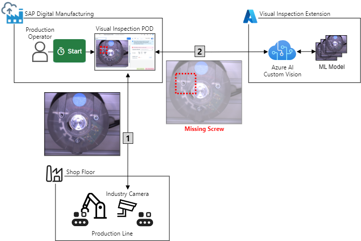
Figure 1: VI scenario with a business process extension on Azure
Figure 2 shows the details of the VI solution based on the key tenets of the reference architecture from part I:
- The asynchronous request-reply and queue-based load leveling messaging patterns are implemented in the extension's core data transformation and service orchestration logic as loosely-coupled microservices using Azure Event Hubs for asynchronous messaging
- The API Gateway pattern uses an Azure API management (APIM) gateway instance to expose the extension's single-entry point and manages cross-cutting concerns like authentication and request throttling
- Internal communication between the microservices and core platform services uses the Azure backbone with Azure private endpoints
- Microsoft Entra ID and Azure Key Vault enforce access control and provide a secure store for confidential data
- Azure AI Custom Vision enhances the extension's core platform services to customize and embed computer vision image analysis for the VI scenario
- Integration with SAP DM is using a destination in the SAP Business Technology Platform (BTP) for sending outbound requests to the extension, and the SAP DM inspection log API for returning the results
The reference architecture does not mandate a specific Azure compute service for the extension's microservices. For event-driven scenarios like in VI with short-lived processes that analyze camera pictures under (near) real-time conditions, Azure Functions offer a well-suited runtime for the microservices that can monitor the rate of VI requests from SAP DM to determine whether to scale out or scale in. Azure Functions integrate with Azure Event Hubs to create a reliable message processor and orchestrator and offers a wide choice of programming languages for implementing the microservices. To reduce the attack surface, Azure Functions can be configured to make the microservices accessible for inbound traffic only from a virtual private network (VNet) via private endpoints to avoid expose on the Internet. For outbound traffic and integration with other Azure services such as Azure Event Hubs and Azure Key Vault, Azure Functions use virtual network integration to call the private endpoints of these services securely over the internal Azure backbone.

Figure 2: VI scenario solution architecture
Before you start with the tutorial, the following step-by-step walkthrough will help you to understand the details of the integration with SAP DM, the extension's architecture, and the implementation details of the microservices:
- The production operator opens the URL to the Production Operator Dashboard (POD) for VI in SAP DM in a browser
- SAP DM redirects the operator to the trusted SAP Cloud Identity Services tenant for authentication
- Upon successful login, the operator selects an SFC in the POD and clicks the Start button to perform the inspection of a valve head for missing screws.
- This triggers the execution of the associated production process for VI.
- The first step in the production process takes the picture of the valve head by calling the URL of the mocked industry camera that reads the picture from an Azure Blob storage. Using external services in a production process requires to register their APIs in SAP DM's Service Registry, the configuration of a Web Server in SAP DM of type Cloud Services, and creation of a Destination in BTP.
- (a) The destination's URL points to the extension's public IP address domain name. It is of type HTTP and uses the OAuth 2.0 client credentials grant as specified in RCF 6749 to request a JWT access token for the extension from the Entra ID tenant. To authorize the access token request from SAP DM, the destination in BTP stores the client credentials (client ID and secret) from the VI extension's application registration. The destination caches the access token until it expires (default lifetime between 60 and 90 minutes) and requests a new one.
(b) The token is sent in the HTTP authorization header with an GET request to the (simulated) camera URL for taking the picture of the valve head. The APIM gateway checks the token according to the rules defined in the extension's APIM policy. This includes limiting the call rate to a specified number per a specified time period (request throttling), verification of the Entra ID tenant as the trusted issuer and the correct audience in the token that must match the extension's application registration client ID. The APIM policy further adds an function access key required by the Azure Function runtime as thecodequery parameter to the forwarded request. - After successfully passing the inbound APIM policy, the request is forwarded to the function endpoint implementing the
TakePictureRequestmicroservice. This HTTP-triggered function takes as input parameters the SFC and plant identifiers (IDs) of the inspected production order that are used in SAP DM to track the material throughout the manufacturing process. To keep the microservices secured and hidden without making them accessible from public Internet, communication between the APIM gateway and the microservices is only possible via Azure private endpoints that route traffic over the internal Azure backbone. - The
TakePictureRequestmicroservice uses the modulo operator on the SFC and plant IDs to generate a random index number within the range of available camera pictures on the Azure Blob storage, reads the picture from there, and returns it as base-64-encoded JPEG data back to production process in SAP DM. - SAP DM continues to orchestrate the VI production process by passing the picture data to the second step that uses the RequestPictureAnalysis service from the service registry to send the actual request to the extension for analyzing the picture.
- Just as with the first step in the production process, this request is also handled by the web server and destination which reuses the access token if it hasn't been expired.
- The destination sends a POST request to the public endpoint of the APIM gateway which enforces the same inbound APIM policy rules as in step 6a. The request contains the production order context (SFC and plant ID) with the base-64-encoded image data in the body and sends the access token in the authorization header.
- After the request passes the policy rules it is forwarded by the gateway to the RequestPictureAnalysis microservice.
- RequestPictureAnalysis stores the picture in the Blob container of the storage account and adds a new event containing the request data to the
PictureAnalysisRequestsevent hub. Following the asynchronous request-reply pattern, RequestPictureAnalysis returns an HTTP response code202(Accepted) to acknowledge that the picture has been received for processing and to unblock SAP DM from waiting for the analysis results. - The PictureAnalysisProcessor microservice is triggered by the new event from
PictureAnalysisRequestsevent hub. - It decodes the base-64-encoded JPEG image and sends it to the Azure AI Custom Vision service endpoint by calling the Prediction API. The service uses a custom ML model trained with 30 images of the valve head where screws are missing in different sockets. If a missing screw is detected, the response contains one more prediction(s) with a score between 0 and 1 for the probability and the coordinates of a bounding box where the missing screw is located in the picture. The probability is a measure of how confident the underlying model is in its prediction. 0 indicates that the model is not at all confident in its prediction, and 1 indicates that the model is completely confident in its prediction of having successfully identified a missing screw.
- The PictureAnalysisProcessor transforms the results from Azure AI Custom Vision service into the data model of the SAP DM inspection log API before sending them to the
PictureAnalysisResultsevent hub for further processing. - The PictureAnalysisResultProcessor microservice is triggered by the new event in the
PictureAnalysisResultsevent hub. It is responsible to send the results in the event back to SAP DM by calling the SAP DM inspection log API. - Just like when calling an extension endpoints on Azure, invoking the inspection log API also requires a valid access token. This must be requested from SAP DM's OAuth server, the XSUAA service in SAP BTP. Similar to Entra ID, XSUAA generates the client credentials for the token request as a service key for SAP DM. The service key's client ID and secret are transferred to Azure Key Vault from where the PictureAnalysisResultProcessor can securely access them to send an authorized token request to XSUAA with the OAuth 2.0 client credentials grant.
- The PictureAnalysisResultProcessor sends the results from the picture analysis to SAP DM's inspection log API. This API call is authorized with the XSUAA-issued access token.
- Based on the results returned from the extension, the selected production order in the VI POD is marked as conformant or non-conformant. If the model failed and returned a false prediction, or missed a defect in the picture, the operator can overrule the proposed (non)conformance in the POD.
Prerequisites
To successfully implement the extension scenario in this tutorial you need the following accounts and permissions:
- User that is a member of an SAP BTP global account with a subaccount and space with a service instance for SAP Digital Manufacturing (digital-manufacturing-services) or SAP Digital Manufacturing Test (digital-manufacturing-services-quality) and plan execution for consumption of SAP DM for execution APIs
- User with Contributor (or Owner) and Key Vault Secrets Officer roles in an Azure subscription
The following configuration in SAP DM should be in place before starting the tutorial:
- A destination for SAP DM to call services or cloud processes defined in the production process designer as documented here.
- Plant, material and operation master data is created
- A POD for VI is created following these instructions.
Additionally, make sure you have installed the following tools:
- Install the Terraform Command Line Interface (CLI) (version 1.5.7 or above) for the deployment of the infrastructure resources in BTP and Azure.
- Install the Azure CLI (version 2.50.0 or above)
- Download and install the Microsoft .NET SDK 7.0
- Optional:
- Use a code editor of your choice, e.g. Microsoft Visual Studio Code
- Install the Azure Functions Core Tools for local development of Azure Functions
Finally, checkout the blog post's GitHub repository with the extension code and infrastructure scripts to get started:
git clone https://github.com/raepple/dmc.gitDeploy the infrastructure with Terraform
Terraform is an open-source Infrastructure as Code (IaC) tool from HashiCorp to build, change, and version infrastructure resources across different cloud service providers. It uses a configuration language to describe the desired “end-state” of your infrastructure for running an application. For an SAP DM extension on Azure, Terraform is the tool of choice to define and deploy the required infrastructure in SAP BTP and Azure. It also automates the configuration of the cross-dependencies between BTP and Azure in the scenario: The client credentials (client ID and secret) of the VI extension's application registration in Entra ID must be added to the configuration of the BTP destination. Vice versa, SAP DM's service key credentials are stored encrypted as secrets in Azure Key Vault and referenced in the Azure Function application settings to allow the PictureAnalysisResultProcessor to access them securely when requesting the token from XSUAA.
All Terraform code can be found in the /infra directory of the repository. The files are split per resource type, for example apim.tf for all Azure API management resource.The main.tf file keeps all configuration settings for the providers used in the scenario, and variables.tf maintains a set input variables to customize the infrastructure deployment without changing the resource files. Some of the variables (for example
location for the Azure region) define a default value ('westeurope'), others (for example 'btp_username') don't. The (default) values you want to (change) can be defined in a file that you pass to the terraform CLI. The repository provides a template file that is used in the following steps to automate the infrastructure deployment:| Step | Description | Screenshot |
| 1 | Open a command line and change to the /infra directory in the local copy of the source repository.Run the command terraform init to initializes your working directory. | 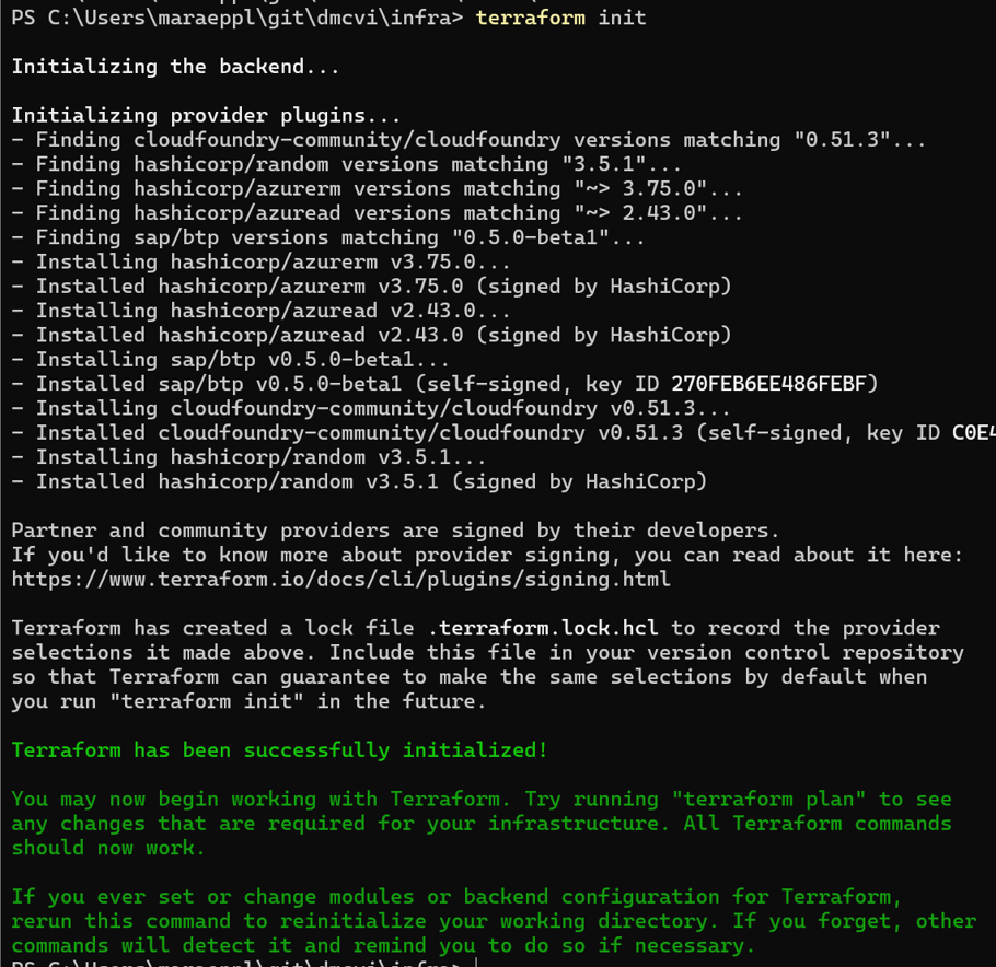 |
| 2 | Login to Azure from the command line with az login with your administrator account.If you have more than one Subscription you can specify the Subscription to use with Terraform via the command az account set --subscription="<SUBSCRIPTION_ID>". | 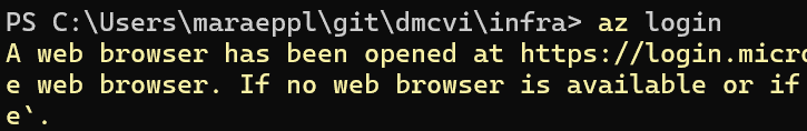 |
| 3 | Rename the input variables template file from dmext.dev.tfvars-template to dmext.dev.tfvars.Note: You can create multiple variable files with specific values for each environment, e.g. dmext.test.tfvars for your test landscape.Open the file in a text editor to specify the values for the variables defined in variables.tf (some define a default value that is not required to be overwritten in your .tfvars files). Set the values according to your target environment, for example configure location to "eastus" if you want to deploy the resources in the East US Azure region (use this link to check for other regions supporting all services required by the VI extension).Note: The resource names are constructed from the values of the variables. The following values are used in this tutorial:
Save the file. |  |
| 4 | Run the command terraform apply -var-file .\dmext.dev.tfvars to create the execution plan for the infrastructure deployment.Answer with 'Y' at the prompt to apply the execution plan. This will take approximately 30 to 45 minutes to complete. Copy the value of the two outputs ( resource_group_name and storage_account_name) after the completion of the command. You will use these values later to deploy the function code. | 
|
After successful completion of the
apply command, all resources in Azure from figure 1 (except from the function app code and the custom vision model) are created with the following Terraform files:- resource_group.tf: The resource group for all VI extension's resources on Azure
- appinsights.tf: Azure Montior application insights instance storing logs and data in an log analytics workspace
- apim.tf: API management instance, API definition for the extension with two operations for the
TakePictureRequestand RequestPictureAnalysis microservices, the APIM policy, and the integration with application insights - application.tf: Entra ID application registration with client credentials (secret) for the VI extension
- cognitive_services.tf: Azure AI Custom Vision service instance for hosting the custom VI model for the scenario. The model will be created and trained manually in a following step.
- eventhub.tf: Event Hub namespace with the
PictureAnalysisRequestsandPictureAnalysisResultsevent hubs - function_app.tf: Azure Function Premium plan and Azure Function app for hosting the functions with the microservices. It is configured with all application settings required by the microservice functions which will be deployed manually in a following step. Confidential application settings reference secrets stored in the Key Vault.
- keyvault.tf: Azure Key Vault with access policies allowing the API management gateway to read the function access key and the function app to access the confidential application settings
- public_ip.tf: Public IP address for the API management gateway
- rbac.tf: Role assignment to built-in roles for the managed identities of the API management (Key Vault Secrets User) and function app (Storage Blob Data Contributor, Azure Event Hubs Data Owner, Key Vault Secrets User) instances
- storage_account.tf: Storage account with blob containers for storing the camera pictures. For testing the VI scenario, the pictures taken by the mocked industry camera are read from the Azure storage account. The test pictures are uploaded by this script and partially match or fail the conformance checks of the Azure AI Vustom Vision model, i.e. only a subset has a screw missing in one of the three sockets.
- virtual_network.tf: VNet, network security group (NSG) to filter in- and outbound network traffic to specific ports, and two subnets for the API management instance and function app hosting the microservice (functions)
All required infrastructure resources in BTP are created with the dm.tf file, which are the destination and service key for the SAP DM service instance. In the following steps the remaining resources in SAP DM are created.
Define the AI/ML scenario in SAP DM
Create and activate a visual inspection scenario in SAP DM that uses a non-conformance group and code for the valve heads with a missing screw.
| Step | Description | Screenshot |
| 5 | Log on to the SAP DM launchpad, select your plant, and start the Manage Nonconformance Groups app. Click Create. | 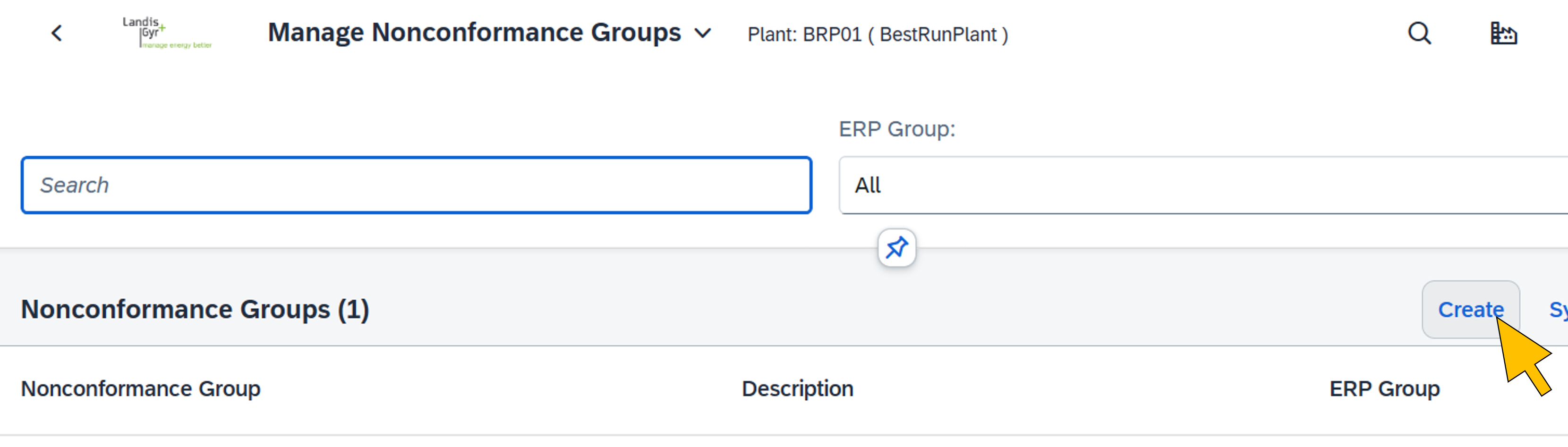 |
| 6 | Enter "VALVE_HEAD_NCG" for the Nonconformance Group Name, and provide a description. Click Create. |  |
| 7 | Start the Manage Nonconformance Codes app. Click Add. |  |
| 8 | Enter the values for the new code:
Scroll down to the Nonconformance Groups settings. |  |
| 9 | Assign the VALVE_HEAD_NCG nonconformance group created in step 6. Click Create. |  |
| 10 | Go to the Manage AI/ML scenarios app. |  |
| 11 | Click Create. |  |
| 12 | Select Predictive Quality: Visual Inspection to start the scenario wizard. |  |
| 13 | On the first step of the scenario wizard (Scenario Definition) enter a scenario name and description of your choice. Click Define to configure the master data for the scenario. |  |
| 14 | Select DME for System. Map plant, material and operation for the scenario. Click Add. | 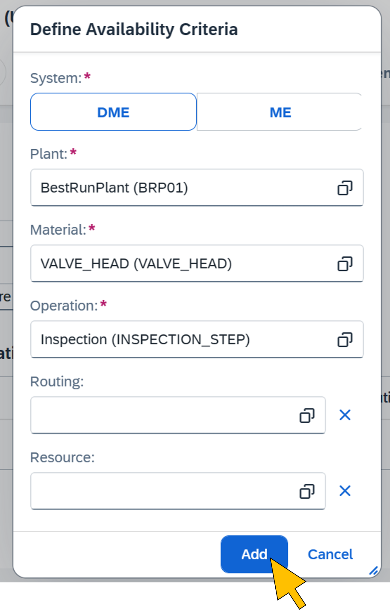 |
| 15 | Click on Step 2. |  |
| 16 | Select Object Detection for the Visual Inspection Type and choose Manual for the Inspection Mode. Continue the wizard by clicking Step 3. |  |
| 17 | In the Scenario Deployment screen, select Add Conformance Class from the Add drop-down menu. |  |
| 18 | Enter the value "OK" for the Class Title, and "0.5" for the Confidence Threshold |  |
| 19 | Select Add Nonconformance Class from the Add drop-down menu | 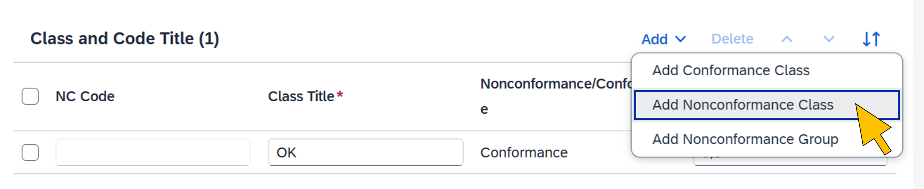 |
| 20 | Search for the MISSING_SCREW non-conformance code created in step 9 and select it from the list. Click OK. |  |
| 21 | Enter the value "MissingScrew" for the Class Title, and "0.5" for the Confidence Threshold. Click Review. |  |
| 22 | Click Save and Activate. | 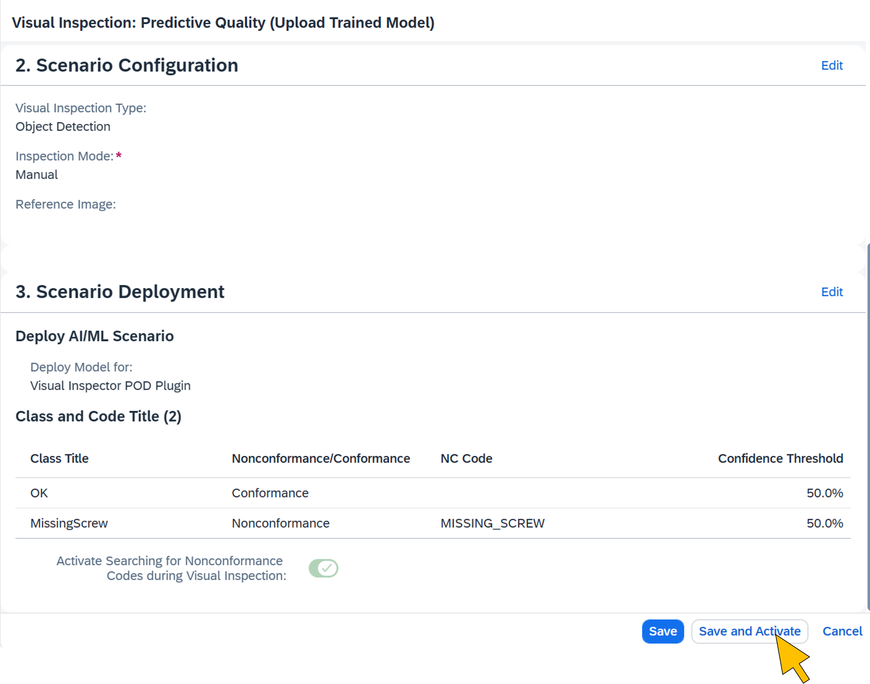 |
| 23 | The new nonconformance code, group, and AI/ML scenario have been successfully created and activated for your plant. |  |
Create the Web Server for the extension
A web server is required in SAP DM to enable the connection and communication with the VI extension on Azure. It is connected to the SAP DM cloud runtime web server (DMC_Cloud) and uses the SAP BTP destination created earlier with Terraform for calling the extension services.
| Step | Description | Screenshot |
| 24 | Log on to the SAP DM launchpad and go to Manage Web Servers. Click Create. |  |
| 25 | Enter the following values:
Click Create. |  |
| 26 | Switch to the Destinations tab. Click Add. |  |
| 27 | Enter "DM extension" in the search field end click Go. From the Items list, activate the checkbox for the destination with the name constructed from the variable values chosen in step 3 (for example "dmext-vi-destination-dev-we"). Click OK. |  |
| 28 | On the left side, enter "DMC_Cloud" in the search field and hit return. Select the DMC_Cloud Web Server from the search results. |  |
| 29 | Switch to the Connections tab. Click Create. | 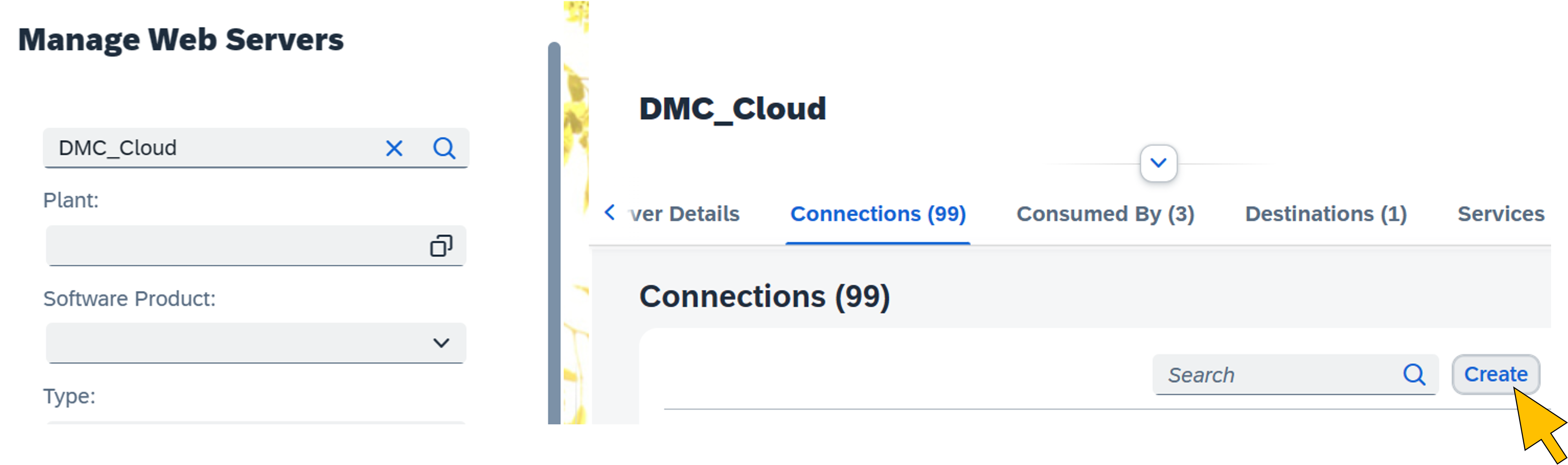 |
| 30 | Enter "dmext-vi-web-server" in the search field and hit return. Select the web server from the search results. |  |
Import and deploy the production process
The production process orchestrates the extension's services on Azure. It is imported into SAP DM from a file in the GitHub repository using the Production Process Designer app. The import also creates the services in the service registry.
| Step | Description | Screenshot |
| 31 | Start the Design Production Processes app. |  |
| 32 | Click Import. | 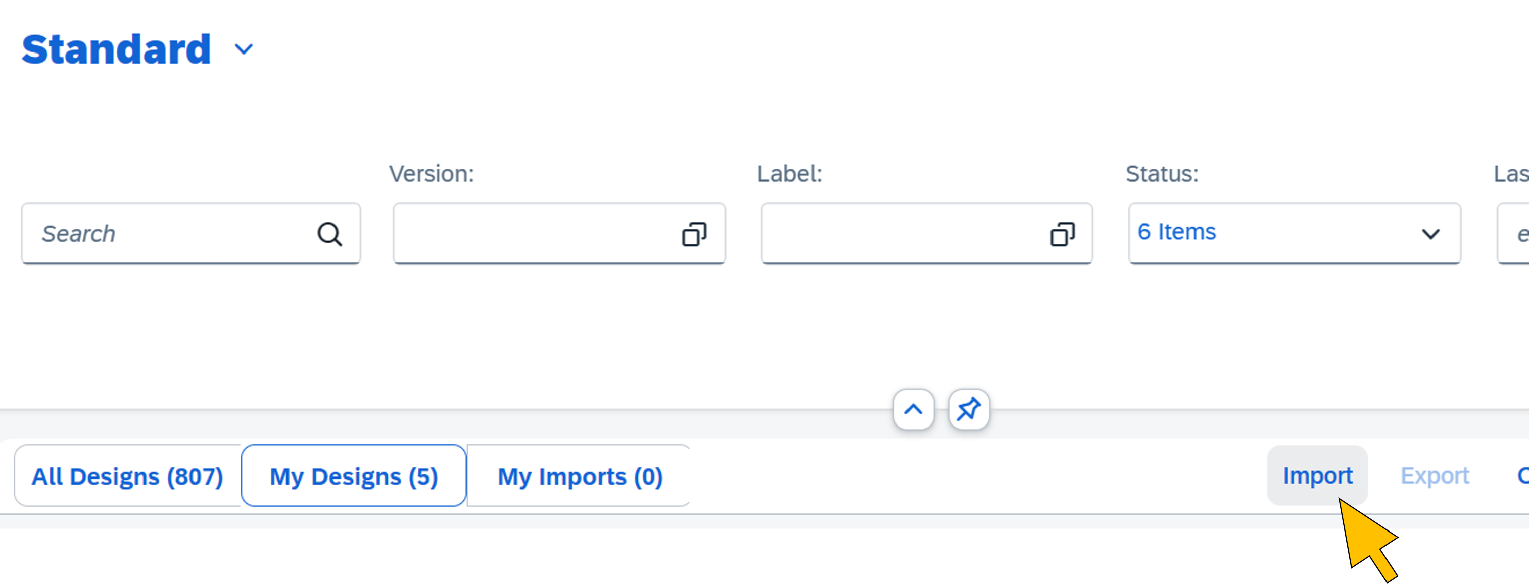 |
| 33 | Select the file dmext-vi-production-process.dmcbak from the GitHub repository folder sapdm. | 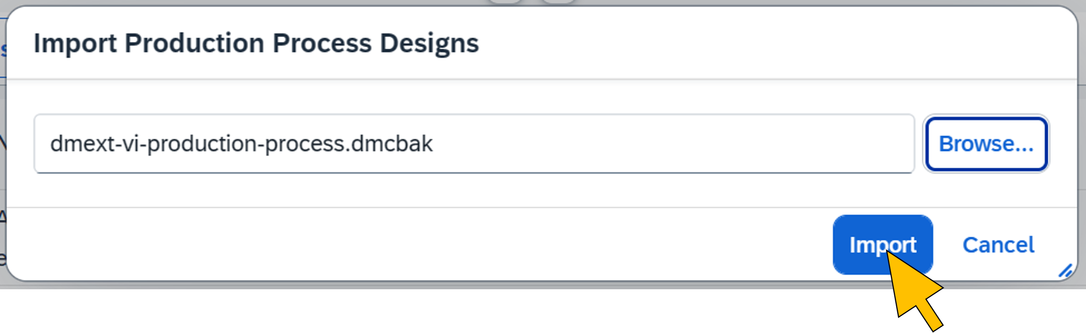 |
| 34 | Enter the password "Abcd1234#" and click Continue. |  |
| 35 | Select the imported process from the list. |  |
| 36 | Click on the first step (dmext-vi-take-picture-srv) in the process diagram to open the settings. |  |
| 37 | Select the destination with the name constructed from the variable values chosen in step 3 (for example "dmext-vi-destination-dev-we"). | 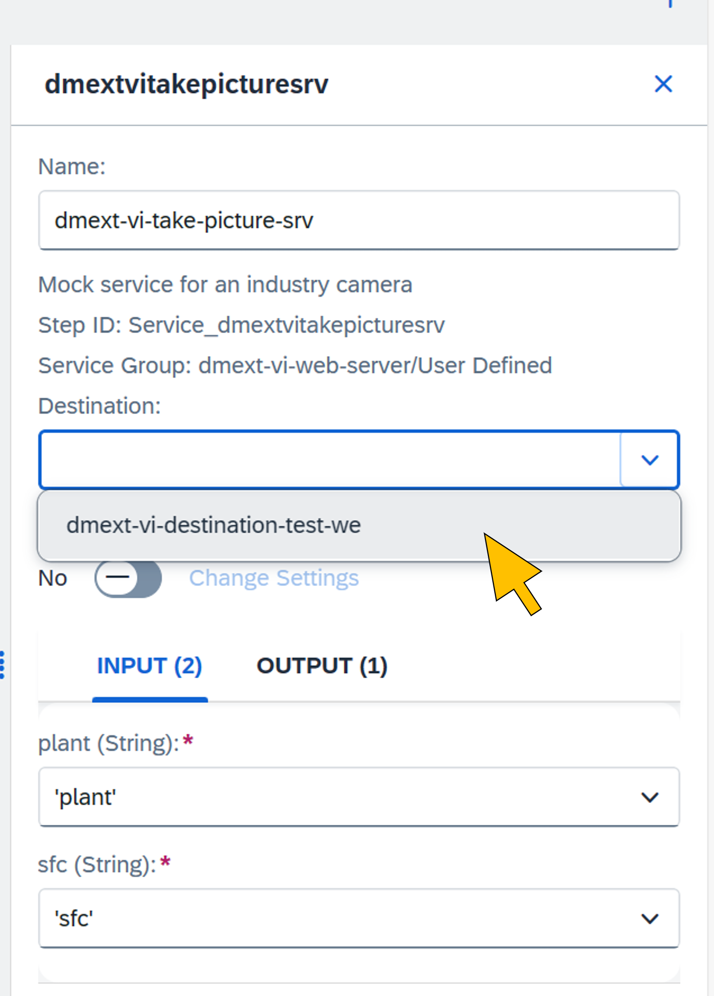 |
| 38 | Click on the second step (dmext-vi-request-picture-analysis-srv) in the process to open the settings. | 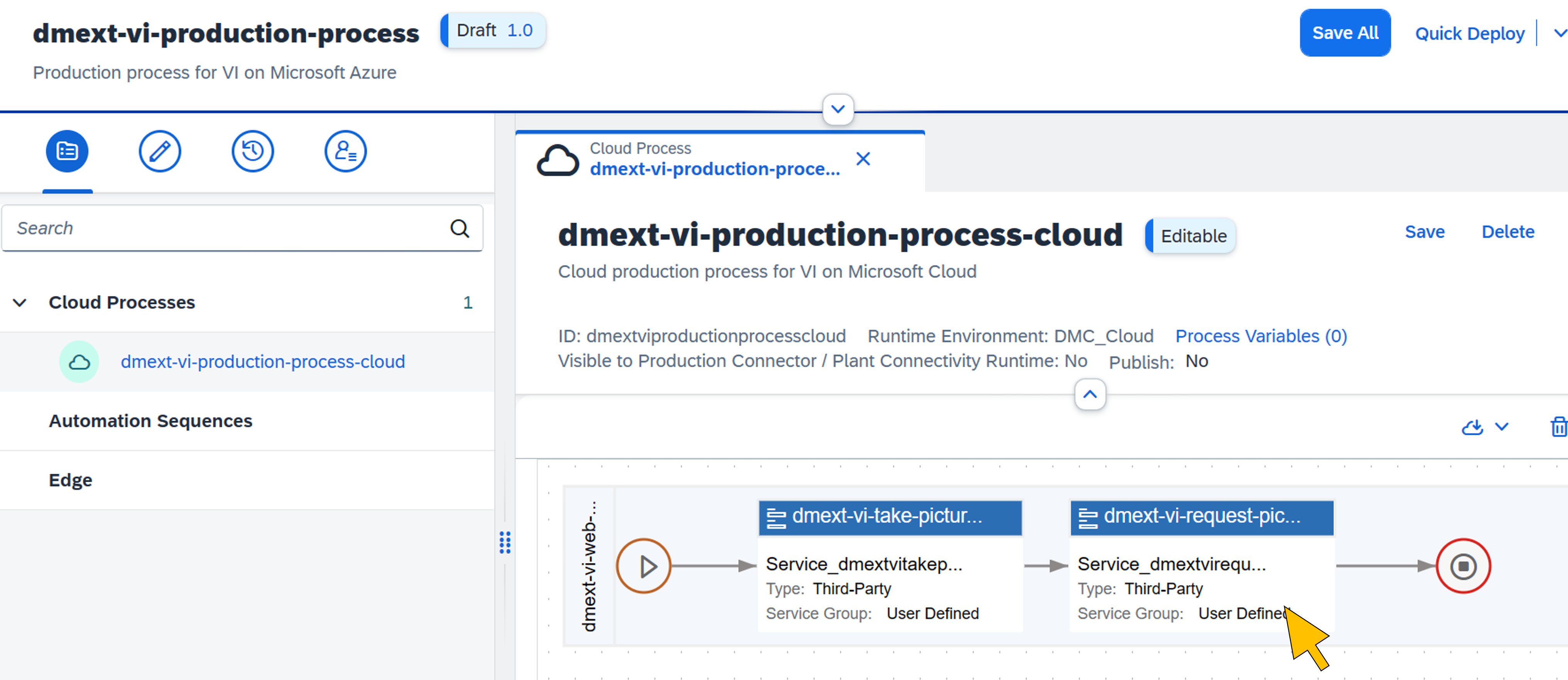 |
| 39 | Repeat step 37 by selecting the destination with the name constructed from the variable values chosen in step 3 (for example "dmext-vi-destination-dev-we"). In the callback entry field, enter the endpoint address for your SAP DM tenant's inspection log API as the callback URL. This is the same value as configured in step 3 for the variable dm_aiml_api_endpoint (e.g. "https://api.eu20.dmc.cloud.sap/aiml/v1/inspectionLog"). Make sure to enclose the URI string with single or double quotes.Click Save All. |  |
| 40 | Click Quick Deploy. |  |
| 41 | Confirm the warning dialog with Deploy and Activate. |  |
| 42 | From the Additional Options menu, select Edit Header. |  |
| 43 | Switch the Publish to Service Registry option to ON. Click Save. |  |
Configure the VI POD to call the production process
The imported production process gets triggered from the VI POD when the production operator select an SFC and clicks the Start button. This setup is configured in the following step using the POD Designer.
| Step | Description | Screenshot |
| 44 | Start the POD Designer app. |  |
| 45 | Select your Visual Inspection POD from the list. |  |
| 46 | Click on the Configuration Panel icon to show the panel. |  |
| 47 | Click on the Start button on the POD's main page to show its configuration in the panel. |  |
| 48 | Click on Assign Actions in the configuration panel. |  |
| 49 | Click Add in the Configure Action Button dialog. |  |
| 50 | Select "Production Process" from the Type drop-down box. In the Type Definition field, select the imported production process. Click Create. |  |
| 51 | Click the Configuration icon of the added production process action. | 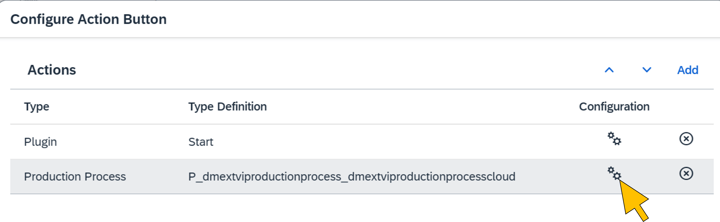 |
| 52 | Map the process input parameters to the following variables:
Click Close. |  |
| 53 | Click Save. |  |
| 54 | Click on the URL button to copy the POD's URL for testing the scenario in the last step of the tutorial. | 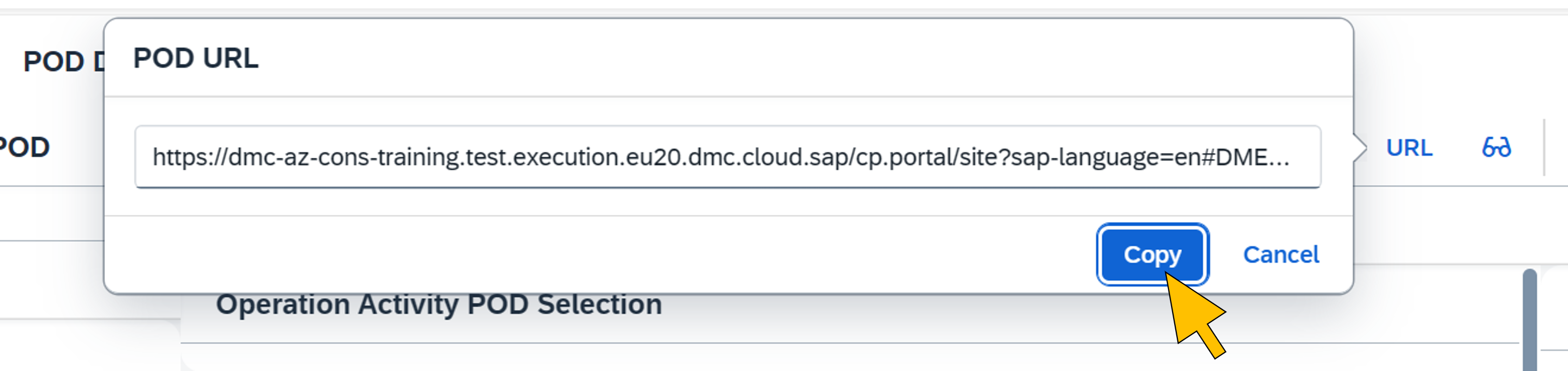 |
Train the ML model
In this tutorial the Azure AI Custom Vision web portal is used to create an object detector model for the VI scenario to detect missing screws in pictures of the valve heads. To build the model, the GitHub repository contains a set of training pictures that are categorized as follows:
- Left screw missing
- Right screw missing
- Lower screw missing
- No screw(s) missing
The training pictures vary by camera angel and exposure to improve the model's quality.
| Step | Description | Screenshot |
| 55 | Logon with your Azure administrator at the Azure AI Custom Vision web portal (https://customvision.ai/) | 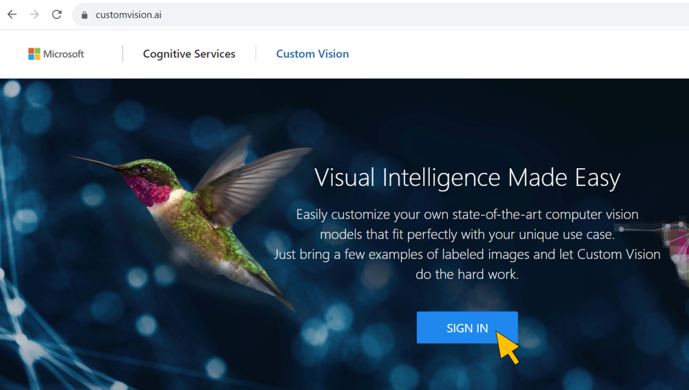 |
| 56 | Confirm the Terms of Service. |  |
| 57 | Click on the NEW PROJECT tile to create a new project. |  |
| 58 | Enter a Name for the new project. For Resource, select the Azure AI Custom Vision service instance created in step 4. Select Object Detection for the Project Type, and General [A1] for the Domain which is optimized for a broad range of object detection tasks. Click Create project. | 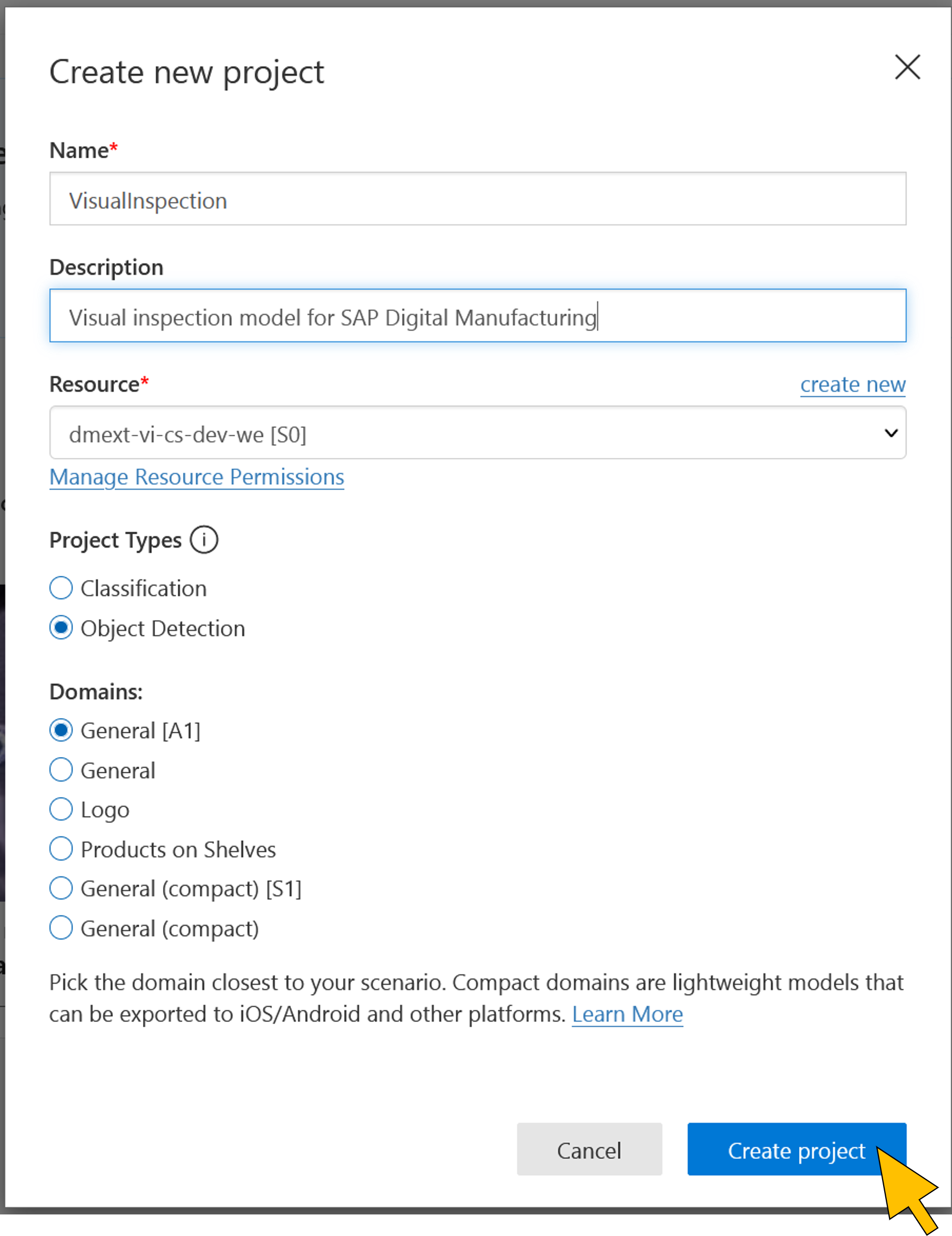 |
| 59 | On the Training images project tab, select Add images. |  |
| 60 | Go to the subfolder dmc\customvision\training\Down in the local copy of the GitHub repository.Select all pictures (10) in the folder. Click Open to upload the pictures. | 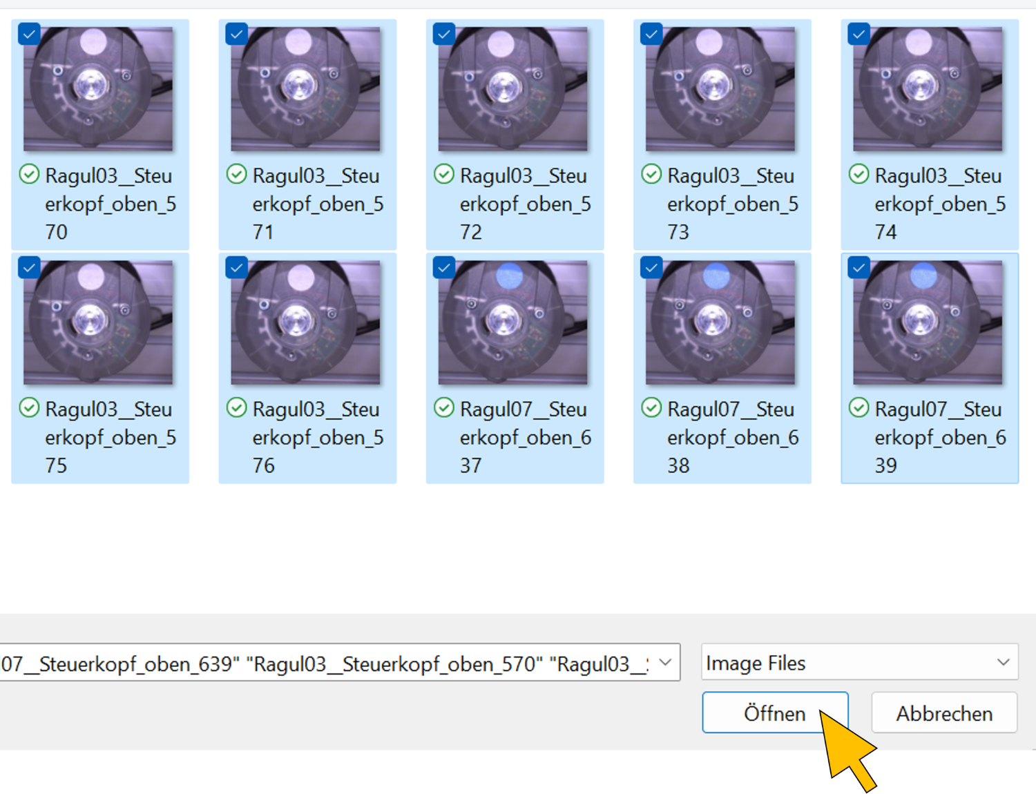 |
| 61 | Click Upload 10 files. |  |
| 62 | After the successful upload, click on the first image. |  |
| 63 | Mark the missing screw in the picture by drawing a rectangle around the empty screw socket in the image. Then, enter "missing screw" as a new tag name with the + button. | 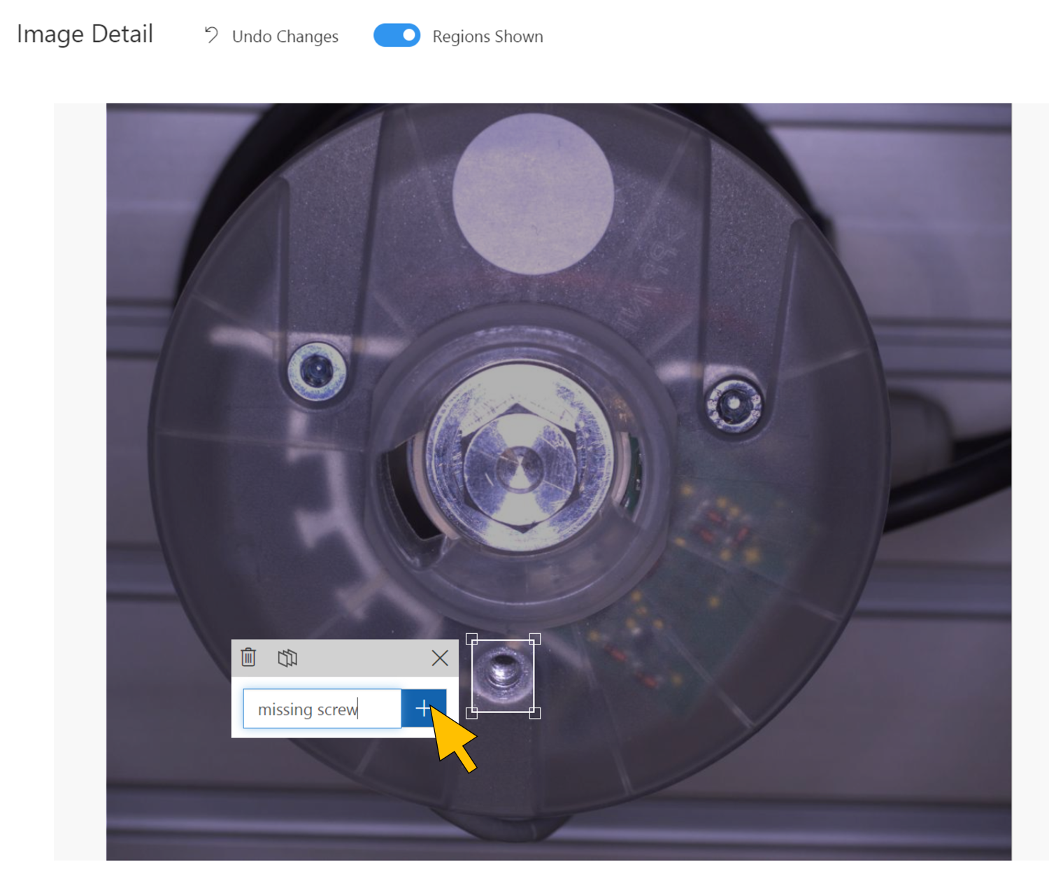 |
| 64 | Click Next to tag the next (untagged) image. |  |
| 65 | Again, mark the missing lower screw in the picture by drawing a rectangle around the empty screw socket in the image. Re-use the existing "missing screw" tag by clicking on it in the drop-down list. Click Next and repeat this step until all uploaded images are tagged with the "missing screw" tag. |  |
| 66 | Repeat steps 58 to 63 by uploading the remaining training images from the local copy of the repository folders Left and Right. These pictures train the model for missing screws in the other sockets. Re-use the "missing screw" tag added in step 61 when tagging the pictures. | 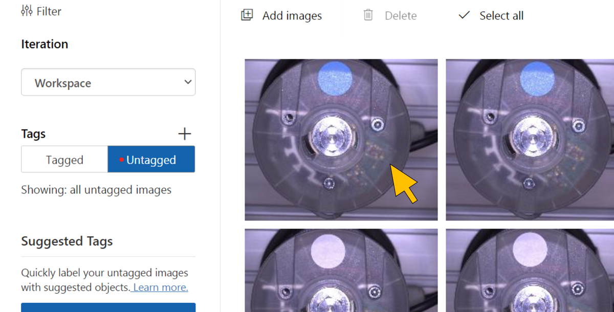 |
| 67 | After completing the upload for all training images you should have a set of 30 training images tagged with "missing screw". |  |
| 68 | Now the model can be trained by clicking on Train. |  |
| 69 | Select the Training Type Quick Training and click Train. |  |
| 70 | Training of the model takes between 15 to 20 minutes. After the completion click Publish to make the model accessible for the PictureAnalysisProcessor with the Prediction API. |  |
| 71 | Keep the default Model name ("Iteration1") and select the same Azure AI Custom Vision service instance chosen in step 56 as the Prediction resource. Click Publish. | 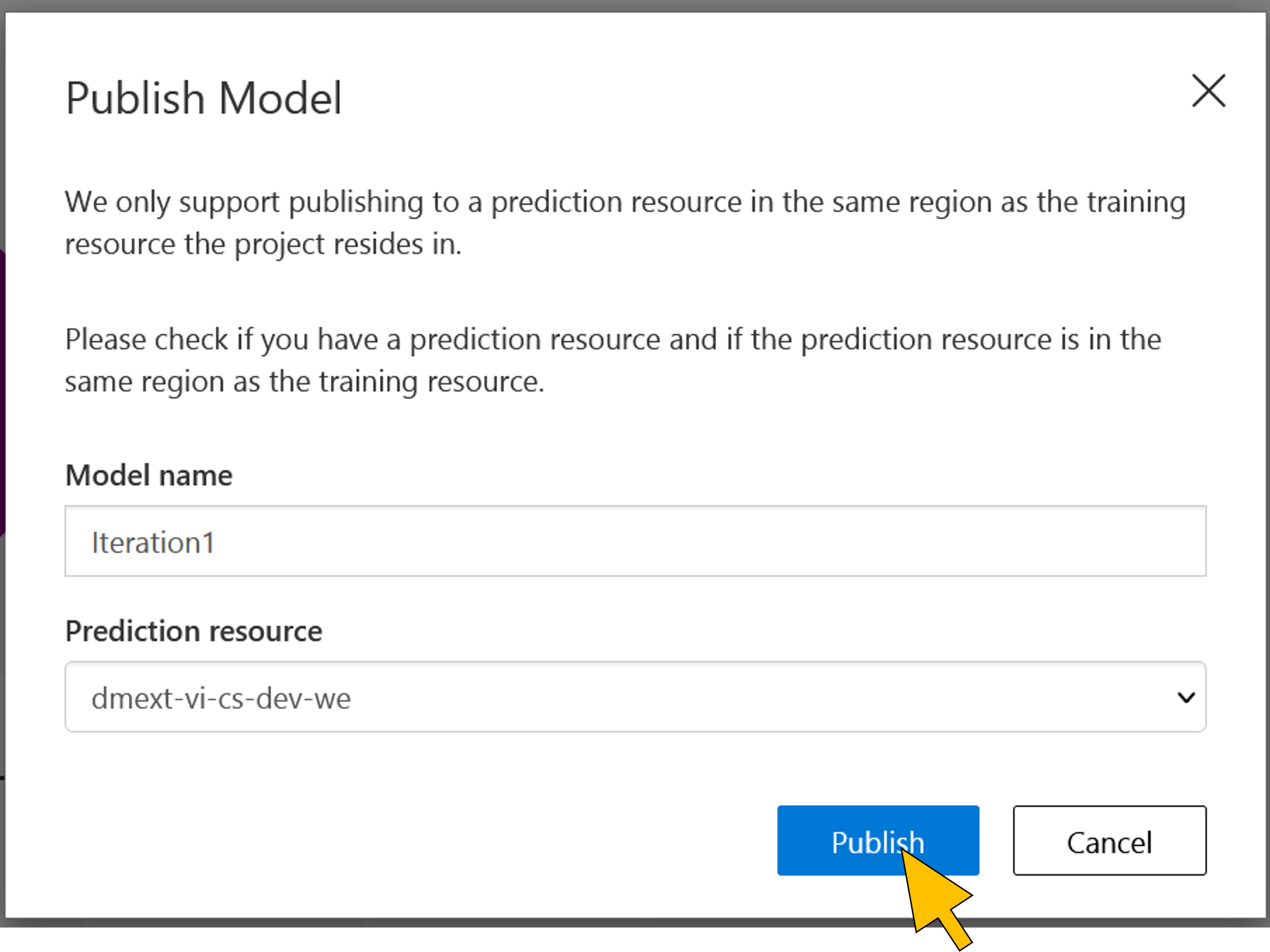 |
| 72 | Click the Settings icon. Copy the value (guid) of the Project Id into the clipboard. This value must be adjusted in the configuration settings of the Azure Function app created in step 4. |  |
| 73 | Logon to the Azure portal (https://portal.azure.com). Go to the Function app in the resource group of this tutorial. |  |
| 74 | Select Configuration from the Settings menu on left side. Click on the application setting with the name COGNITIVE_SERVICES_CUSTOM_VISION_PROJECT_GUID. | 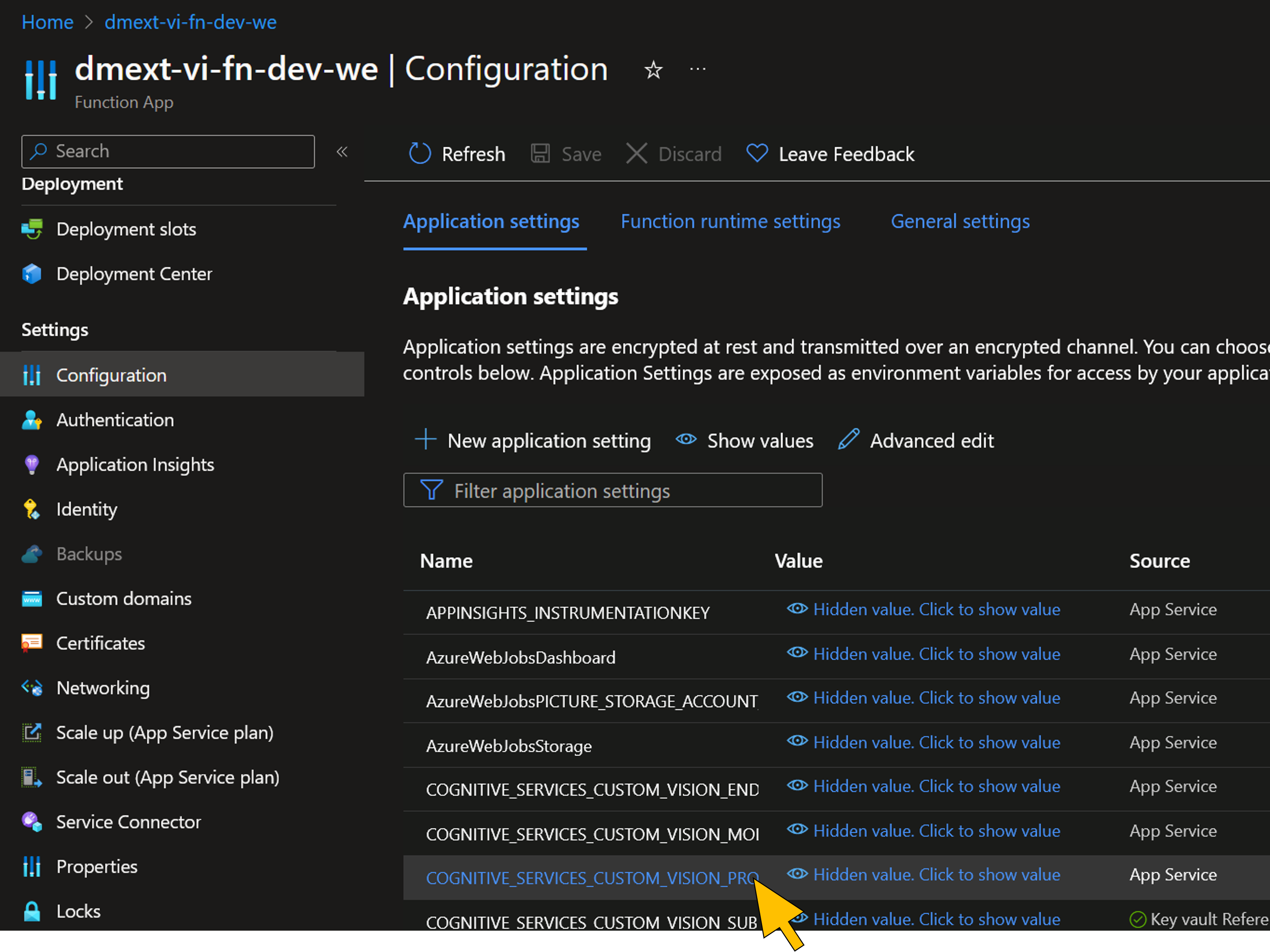 |
| 75 | Overwrite the setting by pasting the value from the clipboard. Click OK. | 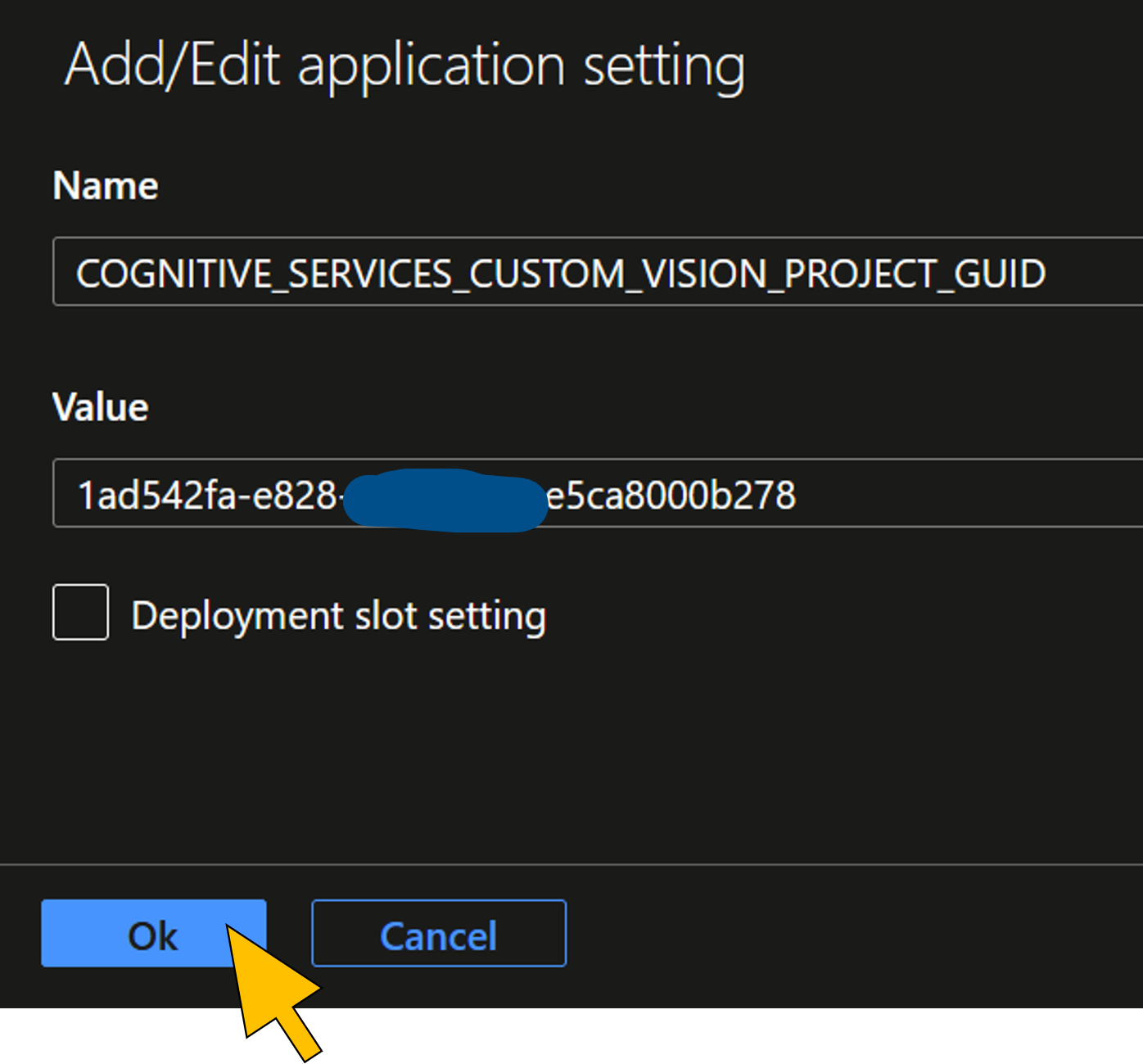 |
| 76 | Click Save. | 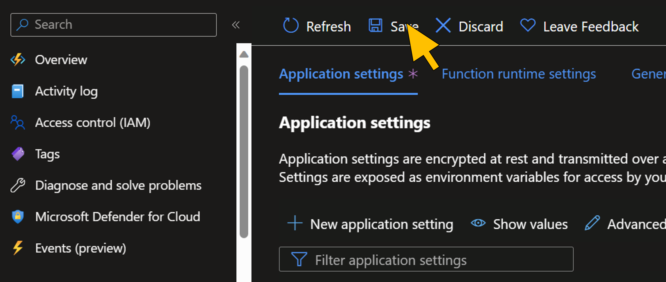 |
Deploy the Azure Functions
The code for the extension microservices is uploaded as a ZIP-compressed archive to the solution's storage account and downloaded from there by the function app runtime using the
WEBSITE_RUN_FROM_PACKAGE application setting. More details and other deployment options for Azure Functions are described here.| Step | Description | Screenshot |
| 77 | Open a PowerShell command line. Change to the folder dmc-extension_cv-orchestrator of the local copy of the GitHub repository. |  |
| 78 | Run the command dotnet publish -o ./deploy |  |
| 79 | Change to the deploy directory withcd ./deployTo create the ZIP archive for the function code upload, run the command Compress-Archive -Path * -DestinationPath dmext.zip |  |
| 80 | Run the command $env:AZURE_STORAGE_KEY="$(az storage account keys list -g <resource_group_name> -n <storage_account_name> --query '[0].value' -o tsv)"to set environment variable for the next command. Replace <resource_group_name> and <storage_account_name> with the values copied in step 4.Then run the command az storage blob upload --account-name <storage_account_name> --container-name deploy --file dmext.zipto upload the ZIP archive with the function code to the deploy storage account blob container. Replace <resource_group_name> with the value copied in step 4. |  |
| 81 | Restart the Azure Function app with the command az functionapp restart --name <function_app_name> --resource-group <resource_group_name>Replace <function_app_name> and <resource_group_name> with the values copied in step 4. |  |
Testing the scenario
Provisioning and configuration of the scenario resources in SAP DM and Azure is now complete for a final test of the scenario.
| Step | Description | Screenshot |
| 82 | Logon as the Production Operator at the VI POD with the URL copied in step 54. Select an SFC in status "In Queue" of the INSPECTION STEP operation activity by activating the checkbox in the first row of the Work List table. Click Start for the selected SFC to trigger the execution of the VI production process. | 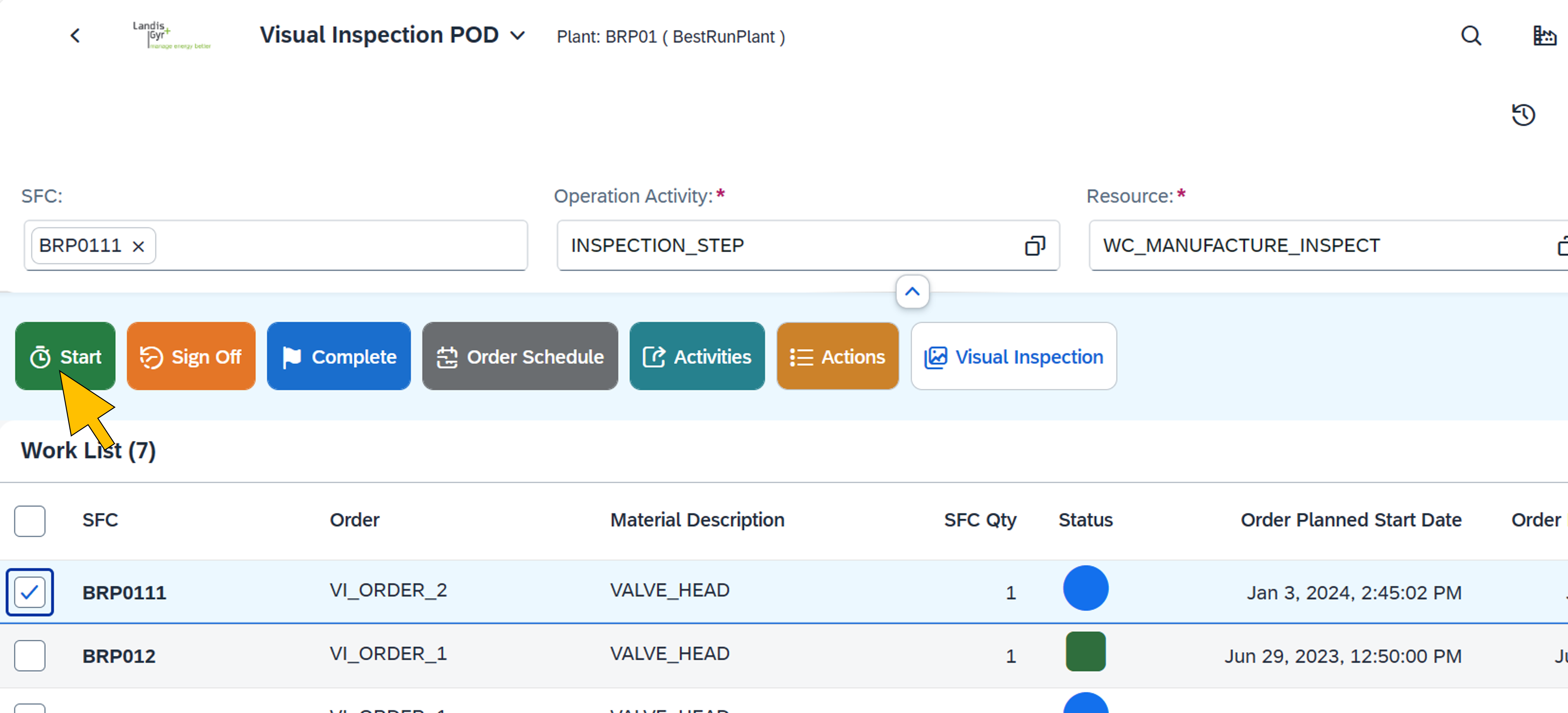 |
| 83 | The system shows the status change of the selected SFC. |  |
| 84 | Wait for a few seconds to complete the visual inspection of the SFC. Click Visual Inspection. |  |
| 85 | The visual inspection page shows the analyzed camera picture. If the Azure AI Custom Vision model identified the valve head being non-conformant, a bounding box with the precision score indicates the missing screw. Click on the magnifier icon. | 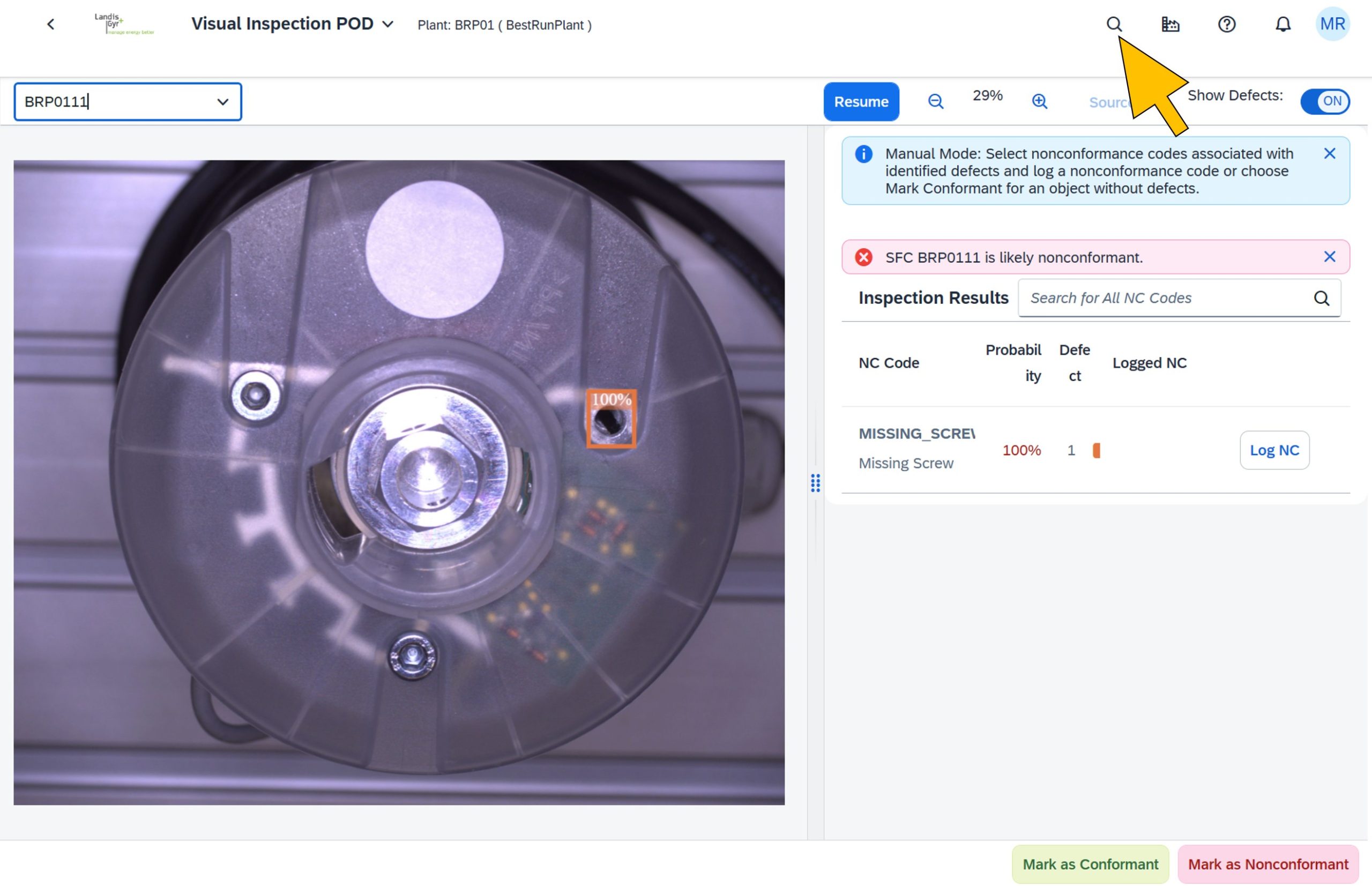 |
| 86 | Start the Monitor Production Process app. |  |
| 87 | Select the most recent process instance of the VI production process from the Process Instances list. | 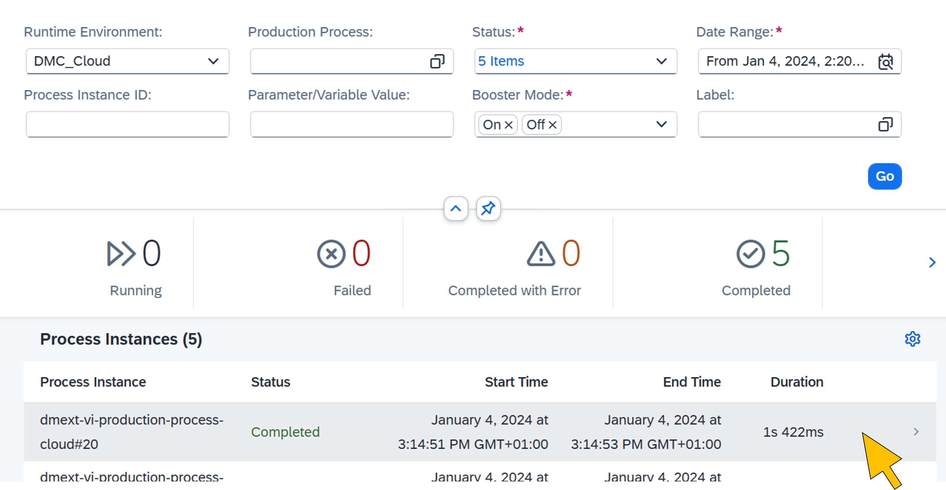 |
| 88 | The process execution details (such as execution time for each step) are shown. |  |
| 89 | To verify the execution details of the extension on Azure, login to the Azure portal (https://portal.azure.com). Select the Function App (e.g. with name "dmext_vi_fn_dev_we") of the VI extension from the list of resources. |  |
| 90 | On the Function App Overview page, click Invocations and more for the PictureAnalysisProcessor function. | 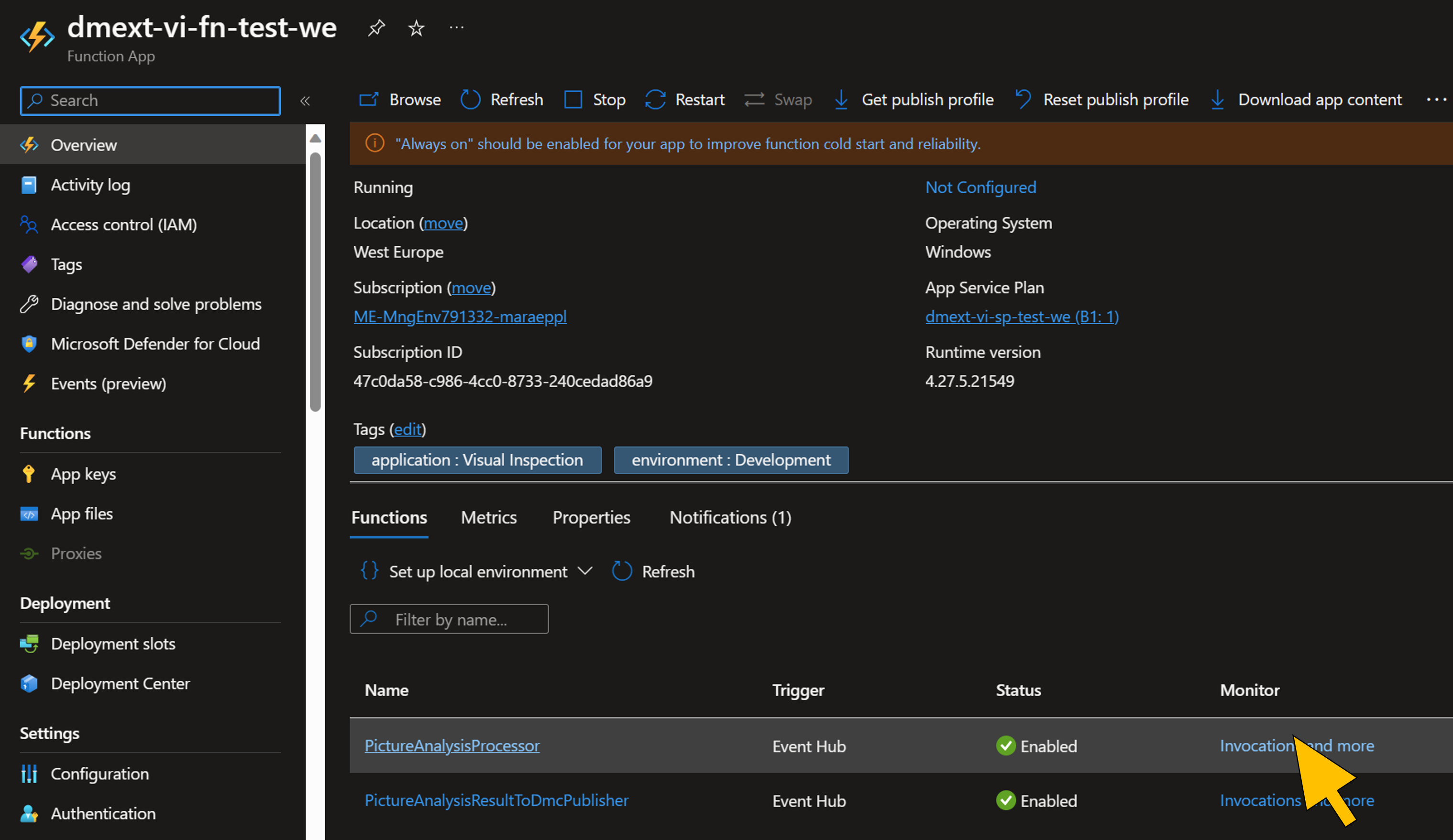 |
| 91 | Select the most recent invocation from the list of Invocation Traces. |  |
| 92 | Find the trace in the list that logs the precision score of the non-conformance found in the camera picture. It should match the bounding box value in the VI POD. |  |
Summary and next steps
With the last step you've successfully completed the implementation of the SAP DM extension on Azure for a visual inspection scenario following the architectural guidelines from part I . In addition, most of the infrastructure deployment and configuration has been scripted using Terraform to automate most of the setup, which also helps to stay consistent across development, test and production environments and enables tracking of previous infrastructure versions.
The next part(s) of this blog series will look into further important topics to make the scenario enterprise-ready. These include GitOps and DevOps automation, and functional enhancements of the scenario such as implementing a feedback cycle to continously improve the AI/ML model based on the conformance/nonconformance decision made by the Production Operator in the VI POD. So stay tuned and send us your feedback.
- SAP Managed Tags:
- SAP Digital Manufacturing,
- SAP S/4HANA,
- SAP Supply Chain Management,
- SAP Business Technology Platform
You must be a registered user to add a comment. If you've already registered, sign in. Otherwise, register and sign in.
Labels in this area
-
Automation
1 -
Billing plan
1 -
Milestone
1 -
Monitoring
1 -
PFAS
1 -
SAP DM
1 -
SAP DMC
1 -
SAP Production Connector
1 -
SPC Control Charts
1
Related Content
- Quick Start guide for PLM system integration 3.0 Implementation in Product Lifecycle Management Blogs by SAP
- 2024 SAP Digital Manufacturing Assets: IVJs, videos and blog posts in Product Lifecycle Management Blogs by SAP
- A day in the life of Mike, a Shop Floor Worker using SAP Digital Manufacturing in Product Lifecycle Management Blogs by SAP
- Extending SAP Digital Manufacturing with Azure, Part I: Reference architecture in Product Lifecycle Management Blogs by Members
Top kudoed authors
| User | Count |
|---|---|
| 2 | |
| 1 | |
| 1 | |
| 1 | |
| 1 |