
- SAP Community
- Products and Technology
- Technology
- Technology Blogs by SAP
- Characterization of Ship Trajectories in the Marit...
Technology Blogs by SAP
Learn how to extend and personalize SAP applications. Follow the SAP technology blog for insights into SAP BTP, ABAP, SAP Analytics Cloud, SAP HANA, and more.
Turn on suggestions
Auto-suggest helps you quickly narrow down your search results by suggesting possible matches as you type.
Showing results for
rafael_pacheco
Participant
Options
- Subscribe to RSS Feed
- Mark as New
- Mark as Read
- Bookmark
- Subscribe
- Printer Friendly Page
- Report Inappropriate Content
09-21-2023
5:10 AM
Motivation
Navies around the world aim at developing methodologies to better understand vessel behavior in the maritime domain in order to be effective in their operations. The first step for this understanding is the ability to track the vessel in real time. Vessels are tracked via satellite navigation system operating as part of a radionavigation-satellite service, e,g, GPS, Glonass, automatic identification systems (AIS), radar systems, and other sensor tools. Figure 1 shows the tracking of vessels moving along specific maritime corridors at a given time [1]. Position reports for each vessel are broadcasted frequently depending on the vessel speed, and these range between two to ten seconds if the vessel is moving or every three minutes if the vessel is at anchor. Considering that about 50,000 ships sail in the ocean each day, the amount of data available from tracking is quite large, rendering a challenge for a human operator to identify vessel behavior useful for maritime domain awareness [2]. Maritime Domain Awareness (MDA) is defined by the International Maritime Organization as the effective understanding of anything associated with the maritime domain that could impact the security, safety, economy, or environment [3].

Figure 1. Vessel tracking illustrating the amount of vessels moving on bodies of water at any given time [1].
The characterization of ship trajectory prediction becomes of utmost importance when the need for its description must be done swiftly due to potential threats. The list below itemizes some scenarios where a quick and accurate characterization for MDA is desirable:
- Security
- Counter-piracy operations
- Fleet and cargo tracking
- Marine environment
- Fishing management
- Oil spill monitoring
- Ship noise pollution
- Species at risk
- Marine safety
- Collision and grounding risks assessment
- Traffic simulation
- Search and rescue
The contribution of this work is the development of an autonomous system that characterizes ship behavior quickly and accurately to achieve MDA in a maritime environment. Our goal is to demonstrate how HANA spatial can be used in conjunction with AIS data to characterize the behavior of ships in the maritime domain, i.e. our interest is in detecting anomalous trajectories as these vessels move along established maritime corridors. Table 1 lists some important types of anomalies of interest in the MDA.
| Course | Speed | Reporting | Location | Maneuver |
| Not towards expected ports | Too low speed for the class of ship | Missing report | Ship position | Transiting vessel |
| Not towards a port | Unattainable speed | No report | Route, zone depth | Loitering |
| Trawling speed in closed zones | Report quality | Legal limit | ||
| Track appears out of anywhere | Proximity |
Table 1. Different types of anomalies commonly found in maritime domain.
Problem description
The ship vessels discussed here navigate in well established shipping trajectories. The creation of these paths start by grouping the trajectories provided by AIS into clusters according to their similarity. Ideally, these trajectories should be grouped by origin and destination without stop. Such trajectory reconstruction can be obtained using for example Dynamic Time Warping (DTW) averaging algorithm which can explicitly address the irregular time sampling of AIS streams with HANA SQL + python via ML [4]. The interested reader is encouraged to read Nidhi Sawhney blog on this topic where HANA PAL + ML using the DTW libraries were used. A similar clustering method [5] has also been implemented in SQL and interested readers should contact Markus Fath to obtain a SQL script.

Figure 2. Snapshot of a vessel moving from Port Klang to Walvis Bay Namibia along a defined corridor. The dashed line is the centerline or ideal ship route, and the shaded area is a buffer zone where ship should remain at all times. Notice that the ship is outside the buffer zone, and this would be an example of an anomalous trajectory.
Here we are interested in the traffic of vessels between two ports that in principle move within a buffer zone shown in Figure 2. The centerline (dashed line of figure 2) has been computed using methodologies similar to those described in the aforementioned paragraph and thus the centerline location is know in advance. Figure 2 exemplifies a known route from Port Klang Malaysia to Walvis Bay Namibia. The red circle in the figure is an arbitrary broadcasted AIS position of a ship. The generated AIS data containing International Maritime Organization (IMO) number, latitude, longitude, course, heading, velocity would look like this:
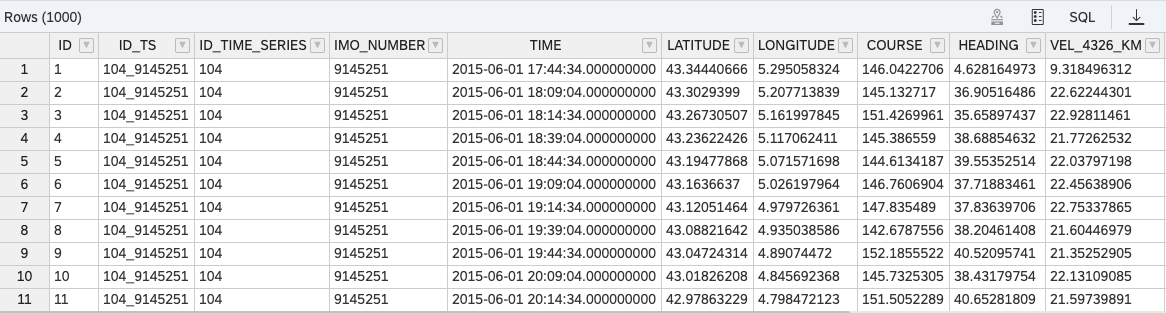
Since the ship is continuously broadcasting the data shown above, a trajectory reconstruction is possible. How one can build a buffer zone is not a topic that will be covered here in detail, but will be addressed in future communications. Suffices to say that one of the methodologies for obtaining such area is based on a Gaussian Process Model [2] where a Gaussian bell curve can be drawn at any point perpendicular to the centerline as shown in figure 2 if a large number of vessel trajectories is available. We note that, due to the winding pattern of the vessel, the spatial referencing of the ship route should align with its trajectory, and not in the geographic coordinate system. The winding trajectories can be more clearly seen in figure 3. The ship motion pattern, e.g. position, velocity, heading or acceleration of the vessel should be described in terms of an axis that is aligned with the route centerline (s) and an axis perpendicular to that centerline (u), as shown in the figure. In that manner, the position, heading, velocity or acceleration of the vessel at any point p(x,y) becomes a function in the new system p(s,u). This can be achieved using coordinate transformation. The local origin (h,k) coincides always with ci, whereas the point p(x,y) in the local coordinate system, i.e. p(s,u), can be determined by taking the intersection of the line from p(x,y) perpendicular to the line formed by the line passing through ci and ci+1. The value of the rotation angle θ can also be deduced, as we have the equation of the line formed by the points ci and ci+1, i.e. we can use the slope of the line m using θ=arctan(m).
 Figure 3. Illustration of the original geographic coordinate system longitude/latitude (x,y) transformed to the route-fitted coordinate system (s,u). The new origin is located at (h,k) and then rotated an angle θ.
More specifically, if the local axes moved along the vessel path, any point p(x,y) they may be brought from the inertial reference to the local reference system by translating them to the new origin (h,k) and then rotating them through the proper angle θ. The equations for the transformation of coordinates are [6]
x = s cos(θ) - u sin(θ) + h,
y = s sin(θ) + u cos(θ) + k.
Conversely, if we want to find the local coordinate values (s,u) given the location of both the point p(x,y) and the origin (h,k) then we can use the following equations:
s = (x - h) cos(θ) + (y - k) sin(θ),
u = -(x - h) sin(θ) + (y - k) cos(θ).
Thus, for any point p(x,y) with longitude and latitude broadcasted by the ship, one can always find the local components in the (s,u) frame of reference and the corresponding heading, velocity and acceleration, provided we know the centerline.
As stated above, given the centerline ci(h,k), any point p(x,y) between ci and ci+1 can be transformed to the local coordinate system. The SQL script in the appendix exemplifies how to do this. The basic idea is to create a line-segment from ci and ci+1 for i and then compute the distance from point p(x,y) to each line-segment and retain that with minimum distance. This guarantees that the point p(x,y) in the local coordinate system (s,u) is between ci and ci+1. The centerline is a set of linestrings, and the objective is to measure the distance from point p(x,y) aiming at obtaining the minimum distance from point p to all the linestrings, and selecting the segment for which the distance is minimum. This can be accomplished by combining the SQL commands ST_LineLocatePoint with ST_LineInterpolatePoint as shown in the SQL script in the appendix. Table CENTERLINE_T is the centerline containing the points ci(h,k), and the table SET_OF_POINTS contains two points that are close to the centerline representing two locations of a vessel moving along the corridor. The script is self contained and can be run in any HANA platform. Visualization can be done using QGIS and connection to a HANA database.
Using the same SQL procedures as in the appendix, we can determine if a trajectory of a vessel is anomalous. Movie 1 shows the trajectory of a vessel traveling from Port Klang to Walvis Bay. The vessel remains within the buffer zone, however, there is a period of time in which the vessel travels back and forth unexpectedly. This anomalous behavior can only be detected when the 'heading' is plotted in the local coordinates (s,u), demonstrating the usefulness of such transformation, as shown in Movie 2, where the change in direction is detected due to the change of sign in the heading. Movie 3 demonstrates how a vessel exits the buffer zone while traveling along the same corridor as in the previous example. Movie 4 shows the 'heading' of the vessel in the (s,u) coordinate system.
https://youtu.be/4ZkM_WeL2GQ
Movie 1. Trajectory of a vessel moving from Port Klang to Walvis Bay Namibia along a defined corridor. The dashed line is the centerline or ideal ship route, and the shaded area is a buffer zone where ship should remain at all times. Notice that the ship moves back and forth within the corridor starting at around t=1'24". This is more evident from movie 2.
Movie 2. Trajectory of a vessel moving from Port Klang to Walvis Bay Namibia. This animation corresponds to that of movie 1. The variable plotted on the vertical axis is the course or 'heading'. A positive value indicates that the motion is in the positive direction along the u-axis. Notice that the ship moves back and forth within the corridor starting at around t~1'24" which is the time at which the values of the heading become negative as demonstrated in movie 1.
https://youtu.be/C7OywxmvApM
Movie 3.Trajectory of a vessel moving from Port Klang to Walvis Bay Namibia along a defined corridor. The dashed line is the centerline or ideal ship route, and the shaded area is a buffer zone where ship should remain at all times. Notice that the ship moves away from the buffer zone in the period of [38",1'24"] approximately. This is also evident from movie 4.
Movie 4. Trajectory of a vessel moving from Port Klang to Walvis Bay Namibia. This animation corresponds to that of movie 3. The variable plotted on the vertical axis is the position u. If the vessel moves away from the buffer zone an alarm can be started facilitating the detection of the anomaly.
Remarks
HANA Spatial is a very powerful tool that allows to tackle complex problems of concern to security agencies. The examples shown here barely touch the capabilities of the Spatial tool. An interesting problem that can be addressed concerns smuggling in MDA. Consider the following scenario: a vessel moving along a corridor meets another vessel to transfer merchandize illegally. SAP HANA Spatial has the tools to determine the minimum distance between these two trajectories, making it possible to detect this anomaly. The number of problems that can be addressed in the area of security using HANA Spatial is quite large, and this tool has been used by our group in the context of stingray operations along with HANA graph aimed at disrupting illegal activities. These examples will be published soon.
References
[1] MarineTraffic: http://www.marinetraffic.com/
[2] Rong, H., Teixeira, A.P., and Guedes Soares, C. (2019) “Ship trajectory uncertainty prediction based on a Gaussian Process model,” Ocean Engineering, 182, 499-511, https://doi.org/10.1016/j.oceaneng.2019.04.024.
[4] Petitjean, F., Forestier, G. and Webb, G., Nicholson, A., Chen, Y. and Keogh, E. (2016). “Faster and more accurate classification of time series by exploiting a novel dynamic time warping averaging algorithm.” Knowledge and Information Systems. 47. 10.1007
[5] Graser. A., Widhalm, P., and Dragaschnig, M. (2020). The M³ massive movement model: a distributed incrementally updatable solution for big movement data exploration. International Journal of Geographical Information Science. doi:10.1080/13658816.2020.1776293.
[6] Analytic Geometry by C. H. Lehmann; Publisher, J. Wiley & sons, 1942.
APPPENDIX
-- Set the schema to your schema

set schema "MY_SCHEMA";

--Center line

DROP TABLE "CENTERLINE_T";

CREATE COLUMN TABLE "CENTERLINE_T" (

	"ID" BIGINT PRIMARY KEY,

	"LONGITUDE" DOUBLE,

	"LATITUDE" DOUBLE

);


-- From Marseille	43.3	5.4

INSERT INTO CENTERLINE_T VALUES (0,5.312426,43.346408);

INSERT INTO CENTERLINE_T VALUES (1,5.29478294988151,43.3465119356896);

INSERT INTO CENTERLINE_T VALUES (2,5.20646409115725,43.3038428464997);

INSERT INTO CENTERLINE_T VALUES (3,5.11597604208007,43.2312333393509);

INSERT INTO CENTERLINE_T VALUES (4,5.02558583275567,43.1576157795945);

INSERT INTO CENTERLINE_T VALUES (5,4.93505780691299,43.0859922500052);

INSERT INTO CENTERLINE_T VALUES (6,4.84454646989727,43.0133649155899);

INSERT INTO CENTERLINE_T VALUES (7,4.75448583253854,42.9429826851554);

INSERT INTO CENTERLINE_T VALUES (8,4.66372850407285,42.8720931523259);

INSERT INTO CENTERLINE_T VALUES (9,4.5731827967412,42.7967262336458);

INSERT INTO CENTERLINE_T VALUES (10,4.48272582122656,42.7256642512231);

INSERT INTO CENTERLINE_T VALUES (11,4.39194954391896,42.6547439006828);

INSERT INTO CENTERLINE_T VALUES (12,4.30155363637234,42.5806325165254);

INSERT INTO CENTERLINE_T VALUES (13,4.21143447612965,42.5087623189113);

INSERT INTO CENTERLINE_T VALUES (14,4.12108489230371,42.4357296659927);

INSERT INTO CENTERLINE_T VALUES (15,4.03048960200102,42.366039096101);

INSERT INTO CENTERLINE_T VALUES (16,3.94435677453802,42.2993597828691);

INSERT INTO CENTERLINE_T VALUES (17,3.85823700825898,42.2349566000536);

INSERT INTO CENTERLINE_T VALUES (18,3.82342684988485,42.2077685611901);

INSERT INTO CENTERLINE_T VALUES (19,3.78855722349429,42.1817350575937);

INSERT INTO CENTERLINE_T VALUES (20,3.75322397494839,42.1570195217015);

INSERT INTO CENTERLINE_T VALUES (21,3.7185194994536,42.1279736139035);

INSERT INTO CENTERLINE_T VALUES (22,3.68392474930694,42.101054195975);

INSERT INTO CENTERLINE_T VALUES (23,3.64884229015929,42.0735698733284);

INSERT INTO CENTERLINE_T VALUES (24,3.61391362936033,42.0473489345615);

INSERT INTO CENTERLINE_T VALUES (25,3.55424576178978,42.0050481250358);

INSERT INTO CENTERLINE_T VALUES (26,3.49443541066158,41.9619566995834);

INSERT INTO CENTERLINE_T VALUES (27,3.43438133786127,41.9198320115124);

INSERT INTO CENTERLINE_T VALUES (28,3.40588816501821,41.898286993716);

INSERT INTO CENTERLINE_T VALUES (29,3.37733061200908,41.8745846255344);

INSERT INTO CENTERLINE_T VALUES (30,3.34864006612884,41.8521622793468);

INSERT INTO CENTERLINE_T VALUES (31,3.3198320178426,41.8307729483745);

INSERT INTO CENTERLINE_T VALUES (32,3.29113428559355,41.8085383715922);

INSERT INTO CENTERLINE_T VALUES (33,3.262850265458,41.7838951569004);

INSERT INTO CENTERLINE_T VALUES (34,3.2341577767413,41.7625620712848);

INSERT INTO CENTERLINE_T VALUES (35,3.2052549710984,41.7407243870093);

INSERT INTO CENTERLINE_T VALUES (36,3.18000863430479,41.7218611137919);

INSERT INTO CENTERLINE_T VALUES (37,3.1550184010079,41.7012228613665);

INSERT INTO CENTERLINE_T VALUES (38,3.1297240301718,41.6822367760629);

INSERT INTO CENTERLINE_T VALUES (39,3.1071341017266,41.6667423826238);

INSERT INTO CENTERLINE_T VALUES (40,3.08488716293877,41.6496051454507);

INSERT INTO CENTERLINE_T VALUES (41,3.06230506512091,41.6306948932272);

INSERT INTO CENTERLINE_T VALUES (42,3.03955560467501,41.6147271436459);

INSERT INTO CENTERLINE_T VALUES (43,3.01721410623882,41.5974276683449);

INSERT INTO CENTERLINE_T VALUES (44,2.99415773496378,41.5892137167406);

INSERT INTO CENTERLINE_T VALUES (45,2.9711632049821,41.5796350648133);

INSERT INTO CENTERLINE_T VALUES (46,2.9483782006771,41.5708115156793);

INSERT INTO CENTERLINE_T VALUES (47,2.92555458175005,41.5617150875598);

INSERT INTO CENTERLINE_T VALUES (48,2.89402944822796,41.5517987957343);

INSERT INTO CENTERLINE_T VALUES (49,2.8626405255459,41.5387082770694);

INSERT INTO CENTERLINE_T VALUES (50,2.83124105703982,41.5259329521037);

INSERT INTO CENTERLINE_T VALUES (51,2.81929215070755,41.521508889919);

INSERT INTO CENTERLINE_T VALUES (52,2.80767418097032,41.5163552498065);

INSERT INTO CENTERLINE_T VALUES (53,2.79601646085585,41.5121851612954);

INSERT INTO CENTERLINE_T VALUES (54,2.78413259279182,41.506777738238);

INSERT INTO CENTERLINE_T VALUES (55,2.77217611755999,41.5032386051942);

INSERT INTO CENTERLINE_T VALUES (56,2.76052379887625,41.4998406591081);

INSERT INTO CENTERLINE_T VALUES (57,2.74864101647652,41.4933158460003);

INSERT INTO CENTERLINE_T VALUES (58,2.73692835774761,41.4899366991848);

INSERT INTO CENTERLINE_T VALUES (59,2.7054727490295,41.4768351356004);

INSERT INTO CENTERLINE_T VALUES (60,2.67366460394507,41.4658224889225);

INSERT INTO CENTERLINE_T VALUES (61,2.64205825810219,41.4531333100418);

INSERT INTO CENTERLINE_T VALUES (62,2.62234572829692,41.4483183484217);

INSERT INTO CENTERLINE_T VALUES (63,2.60270757673597,41.4415271939976);

INSERT INTO CENTERLINE_T VALUES (64,2.58297118148149,41.4320959807162);

INSERT INTO CENTERLINE_T VALUES (65,2.56317094920638,41.4238912727103);

INSERT INTO CENTERLINE_T VALUES (66,2.54324614034695,41.4180281338177);

INSERT INTO CENTERLINE_T VALUES (67,2.52381341956641,41.4106845528295);

INSERT INTO CENTERLINE_T VALUES (68,2.50396237094268,41.4017783872365);

INSERT INTO CENTERLINE_T VALUES (69,2.4841646014734,41.3965830942732);

INSERT INTO CENTERLINE_T VALUES (70,2.46430247367212,41.3909872339004);

INSERT INTO CENTERLINE_T VALUES (71,2.44466710837234,41.3820896562882);

INSERT INTO CENTERLINE_T VALUES (72,2.42488694665846,41.3743557721566);

INSERT INTO CENTERLINE_T VALUES (73,2.4049339391226,41.3666287952576);

INSERT INTO CENTERLINE_T VALUES (74,2.3854131790808,41.3616514349662);

INSERT INTO CENTERLINE_T VALUES (75,2.36568060492433,41.3539862192725);

INSERT INTO CENTERLINE_T VALUES (76,2.34586882002276,41.3467706458015);

INSERT INTO CENTERLINE_T VALUES (77,2.33179834288232,41.3408450869874);

INSERT INTO CENTERLINE_T VALUES (78,2.31757233515791,41.3362534449148);

INSERT INTO CENTERLINE_T VALUES (79,2.3037002138505,41.3313406661874);

INSERT INTO CENTERLINE_T VALUES (80,2.28942669739426,41.3254546135461);

INSERT INTO CENTERLINE_T VALUES (81,2.27559905746131,41.3203073060552);

INSERT INTO CENTERLINE_T VALUES (82,2.26152255485747,41.3153048094543);

INSERT INTO CENTERLINE_T VALUES (83,2.24741052785874,41.3088203480598);

INSERT INTO CENTERLINE_T VALUES (84,2.23317346468954,41.3056209350734);

INSERT INTO CENTERLINE_T VALUES (85,2.21917321652098,41.3006364318483);

INSERT INTO CENTERLINE_T VALUES (86,2.20498317620228,41.2959969925359);

INSERT INTO CENTERLINE_T VALUES (87,2.19692238777387,41.2955096096864);

INSERT INTO CENTERLINE_T VALUES (88,2.18886890644395,41.2946469681935);

INSERT INTO CENTERLINE_T VALUES (89,2.1809550431101,41.2950887274183);

INSERT INTO CENTERLINE_T VALUES (90,2.18,41.38);

--ESBCN	Barcelona	41.38	2.18


-- create ST_GEOMETRY

alter table CENTERLINE_T add ("SP_WAYPOINT" ST_GEOMETRY(4326));

UPDATE "CENTERLINE_T" SET "SP_WAYPOINT" = ST_GEOMFROMTEXT('POINT('||"LONGITUDE"||' '||"LATITUDE"||')',4326) ;

-- Convert it from 4326 to 3857

alter table CENTERLINE_T add ("SP_WAYPOINT_3857" ST_GEOMETRY(3857));

UPDATE "CENTERLINE_T" SET "SP_WAYPOINT_3857" = "SP_WAYPOINT".ST_Transform(3857) ;


/***********************************************/

--Point that will be transformed from longitude/latitude to u/s

DROP TABLE "SET_OF_POINTS";

CREATE COLUMN TABLE "SET_OF_POINTS" (

	"ID" BIGINT PRIMARY KEY,

	"ID_TS" VARCHAR(23),

	"ID_TIME_SERIES" INTEGER,

	"IMO_NUMBER" INTEGER,

	"TIME" TIMESTAMP,

	"LATITUDE" DOUBLE,

	"LONGITUDE" DOUBLE,

	"COURSE" DOUBLE,

	"HEADING" DOUBLE,

	"VEL_4326_KM" DOUBLE

);

-- The table SQLPOINT_T could have one or many rows. The following example has two

truncate table SET_OF_POINTS;

INSERT INTO SET_OF_POINTS VALUES ('35','104_9145251','104','9145251','6/2/15 1:39:04','42.1892223','3.797624518','138.2344523','47.2332862','14.95155879');

INSERT INTO SET_OF_POINTS VALUES ('36','104_9145251','104','9145251','6/2/15 1:52:48','42.16333671','3.766471293','147.8861869','45.58043673','14.78044432');

--

alter table "SET_OF_POINTS"  add ("SP_WAYPOINT" ST_GEOMETRY(4326));

UPDATE "SET_OF_POINTS" SET "SP_WAYPOINT" = ST_GEOMFROMTEXT('POINT('||"LONGITUDE"||' '||"LATITUDE"||')',4326) ;


-- This is the table that will take the points from SET_OF_POINTS and send it to the procedure. At the end, there should be a join with the original table

DROP  table "ROUTES_TABLE" ;

CREATE column table "ROUTES_TABLE"  (

	"ID" BIGINT PRIMARY KEY

	,"SP_WAYPOINT" ST_GEOMETRY(4326)

	);


-- SP procedure

DROP TYPE "TT_CENTERLINE" CASCADE;

CREATE TYPE "TT_CENTERLINE" AS TABLE (

	"ID" BIGINT PRIMARY KEY

	,"LONGITUDE" DOUBLE

	,"LATITUDE" DOUBLE

	,"SP_WAYPOINT" ST_GEOMETRY(4326)

	,"SP_WAYPOINT_3857" ST_GEOMETRY(3857)

	);


-- SP procedure

DROP TYPE "TT_POINTS" CASCADE;

CREATE TYPE "TT_POINTS" AS TABLE (

	"ID" BIGINT,

	"X" DOUBLE,

	"Y" DOUBLE

	);


-- SP procedure

DROP TYPE "TT_ROUTES" CASCADE;

CREATE TYPE "TT_ROUTES" AS TABLE (

	"ID" BIGINT PRIMARY KEY

	,"SP_WAYPOINT" ST_GEOMETRY(4326)

	);


/***************/

drop procedure "P_TRANSFORMATION";

CREATE PROCEDURE "P_TRANSFORMATION"(

	  in i_ID  BIGINT

	, in i_point ST_GEOMETRY

	, in input_table TT_ROUTES

	, in input_cl TT_CENTERLINE

	, out o_scoordinate double

	, out o_ucoordinate double)

	LANGUAGE SQLSCRIPT

	READS SQL DATA AS


BEGIN


declare dtp, xpp, ypp  double;

declare point ST_GEOMETRY;

declare point_temp ST_GEOMETRY;

declare ID_TS integer;


--select ID, SP_WAYPOINT into ID_TS, point_temp from :input_table where ID = :i_ID;


OUTPUT_TABLE = select :i_ID as ID, LONGITUDE as X, LATITUDE as Y from :input_cl;

o_scoordinate = 0;

o_ucoordinate = 0;

point  = :i_point.ST_SRID(4326);

--point  = :point_temp.ST_SRID(4326);

xpp = :point.ST_Transform(3857).ST_X();

ypp = :point.ST_Transform(3857).ST_Y();


temp = SELECT L.ID as ID

		, ST_MakeLine(L.SP_WAYPOINT, R.SP_WAYPOINT)  as "SP_WAYPOINT_LINE"

		, L.SP_WAYPOINT as "L_SP_WAYPOINT"

		, R.SP_WAYPOINT as "R_SP_WAYPOINT"

 		, ST_MakeLine(L.SP_WAYPOINT, R.SP_WAYPOINT).ST_LENGTH()  as "LENGTH"

		, ST_MakeLine(L.SP_WAYPOINT_3857, R.SP_WAYPOINT_3857)  as "SP_WAYPOINT_LINE_3857"

		, ST_MakeLine(L.SP_WAYPOINT_3857, R.SP_WAYPOINT_3857).ST_length()  as "LENGTH_3857"

		, L.SP_WAYPOINT_3857.ST_X() - R.SP_WAYPOINT_3857.ST_X() as "DX"

		, L.SP_WAYPOINT_3857.ST_Y() - R.SP_WAYPOINT_3857.ST_Y() as "DY"

		FROM :input_cl AS L INNER JOIN :input_cl AS R ON L.ID = (R.ID-1) ;


--select * from :temp;


temp1 = select ID

		, "LENGTH"

		, "LENGTH_3857"

		, case when "DX" <> 0 then "DY"/"DX" else 9999 end as "SLOPE"

		, "DX"/"LENGTH_3857" as "COS_T"

		, "DY"/"LENGTH_3857" as "SIN_T"

		, "SP_WAYPOINT_LINE_3857".ST_Distance( :point.ST_Transform(3857) ) as "DISTANCE_TO_POINT"

		, "SP_WAYPOINT_LINE_3857".ST_LineLocatePoint(:point.ST_Transform(3857) ) as "LINELOCATEPOINT"

		, "SP_WAYPOINT_LINE"

		, "SP_WAYPOINT_LINE_3857"

		, SUM("LENGTH") OVER (ORDER BY ID) AS "CUMMULATIVE_LENGTH"

		, SUM("LENGTH_3857") OVER (ORDER BY ID) AS "CUMMULATIVE_LENGTH_3857"

		, "L_SP_WAYPOINT"

		, "R_SP_WAYPOINT"	from  :temp;


--select * from :temp1;


temp1a = select case when b."Rank" = 1 then 1  else 0 end as RANK , a.* from :temp1 a

				left join (select row_number() OVER ( order by "DISTANCE_TO_POINT" asc) as "Rank", ID

							from :temp1 ) b

							on a.ID = b.ID  ;


--select * from :temp1a;


temp2 = 	select

		 "ID"

		, "RANK"

		, "L_SP_WAYPOINT".ST_X() as "X_L"

		, "L_SP_WAYPOINT".ST_Y() as "Y_L"

		, "R_SP_WAYPOINT".ST_X() as "X_R"

		, "R_SP_WAYPOINT".ST_Y() as "Y_R"

		, "DISTANCE_TO_POINT"

		, "LINELOCATEPOINT"

--		, "SP_WAYPOINT_LINE_3857".ST_LineInterpolatePoint("LINELOCATEPOINT").ST_AsText() as "INTERPOLATION_POINT_TEXT"

--		, "SP_WAYPOINT_LINE_3857".ST_LineInterpolatePoint("LINELOCATEPOINT") as "INTERPOLATION_POINT"

		, "SP_WAYPOINT_LINE_3857".ST_LineInterpolatePoint("LINELOCATEPOINT").ST_Transform(4326).ST_AsText() as "INTERPOLATION_POINT_TEXT"

		, "SP_WAYPOINT_LINE_3857".ST_LineInterpolatePoint("LINELOCATEPOINT").ST_Transform(4326) as "INTERPOLATION_POINT"

--

		, "COS_T"

		, "SIN_T"

		, "CUMMULATIVE_LENGTH"

		, "CUMMULATIVE_LENGTH_3857"

		, "SP_WAYPOINT_LINE"

		, "SP_WAYPOINT_LINE_3857"

		, "L_SP_WAYPOINT"

		, "R_SP_WAYPOINT"

		, "LENGTH"

		, "LENGTH_3857"	from  :temp1a;


temp3 = select "ID"

				, "RANK"

				, case when "RANK" = 0 then 1 else "LINELOCATEPOINT" end as FACTOR

				, "X_L"

				, "Y_L"

				, "X_R"

				, "Y_R"

				, (:xpp - "INTERPOLATION_POINT".ST_Transform(3857).ST_X()) as "Xp"

				, (:ypp - "INTERPOLATION_POINT".ST_Transform(3857).ST_Y()) as "Yp"

				, (:xpp - "INTERPOLATION_POINT".ST_Transform(3857).ST_X() ) * "COS_T"

				+ (:ypp - "INTERPOLATION_POINT".ST_Transform(3857).ST_Y() ) * "SIN_T"as "Xpp"

--

				, -( :xpp - "INTERPOLATION_POINT".ST_Transform(3857).ST_X() ) * "SIN_T"

				+  ( :ypp - "INTERPOLATION_POINT".ST_Transform(3857).ST_Y() ) * "COS_T"as "Ypp"

--

				, "DISTANCE_TO_POINT"

				, "LINELOCATEPOINT"

				, SUM("LENGTH"*"LINELOCATEPOINT") OVER (ORDER BY ID) AS "CUMMULATIVE_LENGTH_LLP"

				, SUM("LENGTH_3857"*"LINELOCATEPOINT") OVER (ORDER BY ID) AS "CUMMULATIVE_LENGTH_3857_LLP"

				, SUM("LENGTH"* (case when "RANK" = 0 then 1 else "LINELOCATEPOINT" end)) OVER (ORDER BY ID) AS "CUMMULATIVE_LENGTH_RANK"

				, SUM("LENGTH_3857"*(case when "RANK" = 0 then 1 else "LINELOCATEPOINT" end)) OVER (ORDER BY ID) AS "CUMMULATIVE_LENGTH_RANK_3857"

				, "INTERPOLATION_POINT".ST_X() as "h"

				, "INTERPOLATION_POINT".ST_Y() as "k"

				, "INTERPOLATION_POINT_TEXT"

				, "COS_T"

				, "SIN_T"

				, "CUMMULATIVE_LENGTH"

				, "CUMMULATIVE_LENGTH_3857"

				, "SP_WAYPOINT_LINE"

				, "SP_WAYPOINT_LINE_3857"

				, "L_SP_WAYPOINT"

				, "R_SP_WAYPOINT"

				, "INTERPOLATION_POINT"

				, "LENGTH"

				, "LENGTH_3857"	from :temp2;


--select * from :temp3;


select min(DISTANCE_TO_POINT) as MIN_DIST_TO_POINT into dtp from :temp3;

--select * from :temp3 where DISTANCE_TO_POINT = :dtp and  "LINELOCATEPOINT" < 1 ;

-- select  "CUMMULATIVE_LENGTH_RANK","Ypp" into o_scoordinate, o_ucoordinate from :temp3 where DISTANCE_TO_POINT = :dtp  and  "LINELOCATEPOINT" < 1 ;

select  "CUMMULATIVE_LENGTH_RANK_3857","Ypp" into o_scoordinate, o_ucoordinate from :temp3 where DISTANCE_TO_POINT = :dtp  and  "LINELOCATEPOINT" < 1 ;

--o_scoordinate = 0.1234;

--o_ucoordinate = 0.1234;

end;


/***********/

--TEST returns U and S

call "P_TRANSFORMATION"(10000,ST_GeomFromText('Point ( 41.35 2.6)', 4326),"ROUTES_TABLE","CENTERLINE_T",?,?);

call "P_TRANSFORMATION"(10000,ST_GeomFromText('Point ( 41.31472 2.16999)', 4326),"ROUTES_TABLE","CENTERLINE_T",?,?);

call "P_TRANSFORMATION"(10000,ST_GeomFromText('Point ( 41.34598643564281 2.325704774470081)', 4326),"ROUTES_TABLE","CENTERLINE_T",?,?);

/***********/


/***********************************************

The following script sends from one to many points to be transformed to the local coordinate system U,S

It uses P_TRANSFORMATION

***********************************************/

drop table "TEMPXXX";

CREATE COLUMN TABLE "TEMPXXX" (

	"IDT" INTEGER

	,"S" DOUBLE

	,"U" DOUBLE

	);


drop procedure "generate_transformed_coordinates";

create procedure "generate_transformed_coordinates" (  )

        language sqlscript as

begin

declare i, j, nmax, nmin integer;

declare o_s,o_u double;

declare i_point ST_GEOMETRY;


        declare cursor id_cursor for

        select distinct("ID") from "ROUTES_TABLE" where "ID" is NOT NULL;

		select min("ID"),max(ID) into nmin,nmax from "ROUTES_TABLE" where "ID" is NOT NULL;


		truncate table "TEMPXXX";

		sel3 = select * from "TEMPXXX";


		i := nmin;

		j := 1;

		input_centerline = select * from "CENTERLINE_T" order by ID;

		input_routes =  select ID,SP_WAYPOINT from "ROUTES_TABLE" order by ID;

        for id_ts as id_cursor do

        	routes = select * from :input_routes  where ID = :i;

  			select SP_WAYPOINT into i_point from :input_routes  where ID = :i;


	   		call "P_TRANSFORMATION"(id_ts.id,:i_point,:routes,:input_centerline,o_s,o_u);

			sel3."IDT"[j]=:i ;

			sel3."S"[j]=:o_s ;

			sel3."U"[j]=:o_u ;


        	i := i+1;

        	j := j+1;


        end for;

        select * from :sel3;

       	select * from :sel3  into "TEMPXXX";


end;


--send the point(s) to be transformed, from SET_OF_POINTS table

truncate table "ROUTES_TABLE";

insert into "ROUTES_TABLE"

select ID, "SP_WAYPOINT" from "SET_OF_POINTS"    order by ID;

/***************************************/

call "generate_transformed_coordinates" ();

/***************************************/


-- create a new table as SET_OF_POINTS but added S and U

drop table "JOINT_TABLE";

create column table "JOINT_TABLE" as (

	select A.*, B.U, B.S from "SET_OF_POINTS" as A

		join "TEMPXXX" as B

		on A.ID = B.IDT

	);

--Check the table

select * from "JOINT_TABLE";
- SAP Managed Tags:
- Machine Learning,
- SAP Datasphere,
- SAP HANA Cloud,
- Python,
- SAP HANA Graph,
- SAP HANA Spatial
Labels:
1 Comment
You must be a registered user to add a comment. If you've already registered, sign in. Otherwise, register and sign in.
Labels in this area
-
ABAP CDS Views - CDC (Change Data Capture)
2 -
AI
1 -
Analyze Workload Data
1 -
BTP
1 -
Business and IT Integration
2 -
Business application stu
1 -
Business Technology Platform
1 -
Business Trends
1,658 -
Business Trends
93 -
CAP
1 -
cf
1 -
Cloud Foundry
1 -
Confluent
1 -
Customer COE Basics and Fundamentals
1 -
Customer COE Latest and Greatest
3 -
Customer Data Browser app
1 -
Data Analysis Tool
1 -
data migration
1 -
data transfer
1 -
Datasphere
2 -
Event Information
1,400 -
Event Information
67 -
Expert
1 -
Expert Insights
177 -
Expert Insights
301 -
General
1 -
Google cloud
1 -
Google Next'24
1 -
GraphQL
1 -
Kafka
1 -
Life at SAP
780 -
Life at SAP
13 -
Migrate your Data App
1 -
MTA
1 -
Network Performance Analysis
1 -
NodeJS
1 -
PDF
1 -
POC
1 -
Product Updates
4,577 -
Product Updates
346 -
Replication Flow
1 -
REST API
1 -
RisewithSAP
1 -
SAP BTP
1 -
SAP BTP Cloud Foundry
1 -
SAP Cloud ALM
1 -
SAP Cloud Application Programming Model
1 -
SAP Datasphere
2 -
SAP S4HANA Cloud
1 -
SAP S4HANA Migration Cockpit
1 -
Technology Updates
6,873 -
Technology Updates
429 -
Workload Fluctuations
1
Related Content
- Data Quality Audit in Technology Blogs by SAP
- Fast Track your AI Strategy with SAP Business AI in Technology Blogs by SAP
- Transforming SAP Cloud ALM Approvals with KTern.AI Rapid Approve in Technology Blogs by Members
- [SAP BTP Onboarding Series] Joule – Getting Started with Joule and SAP SuccessFactors in Technology Blogs by SAP
- The road to a Sustainable Business: How Large Scale Transformation (LTP) method can lead the way in Technology Blogs by Members
Top kudoed authors
| User | Count |
|---|---|
| 32 | |
| 17 | |
| 15 | |
| 13 | |
| 11 | |
| 9 | |
| 8 | |
| 8 | |
| 8 | |
| 7 |